Link Roads:
Roads created within this editor can be linked together with ’link roads’. Link roads remain attached to the roads they are linked to, such that if the road is translated (moved), the link road will move to accomodate this change, thus keeping them linked. This feature allows the user to create junctions, highway intersections, slip roads etc.
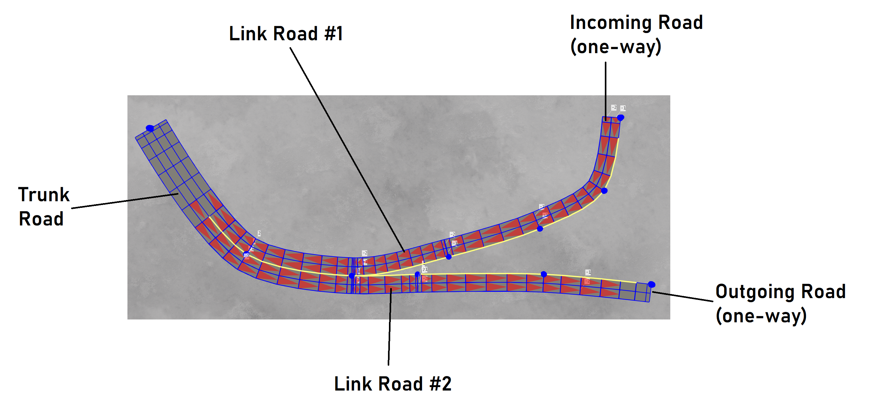
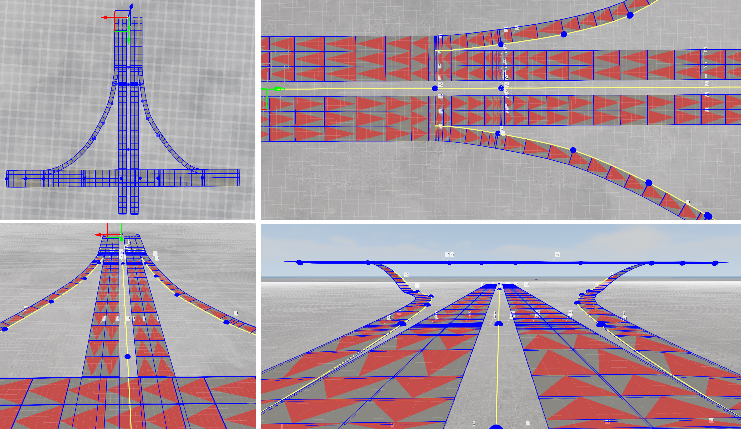
The following image shows a typical simple junction which links a larger trunk road with two smaller one-way roads.
Roads are linked together at the lane level using a dedicated linking mode. This is found in the editor’s main tool window. The buttons relating to road linking are shown in the image below.
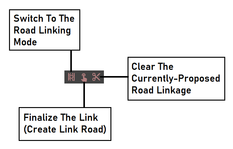
Note: Only the first of these buttons will normally be shown, which, when pressed, will switch the editor into Linking Mode. The user is then requested to design a proposed road linkage, at which time the other buttons will appear as required.
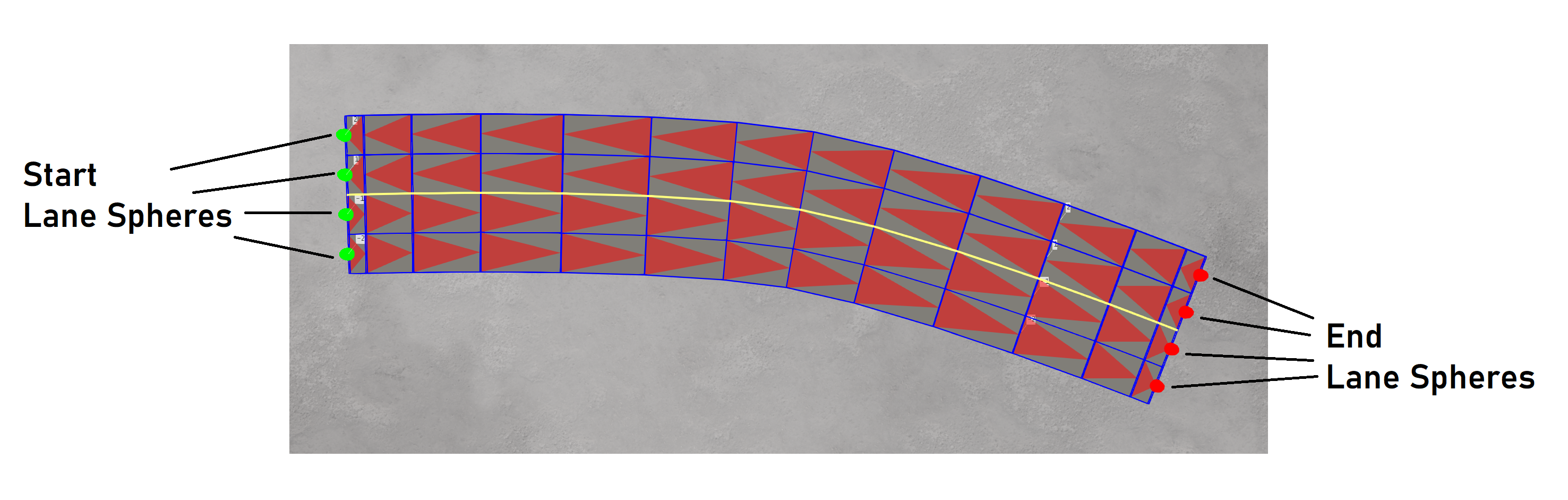
Upon entering the linking mode, the visualisation changes - node spheres are not shown and instead, spheres are shown at the start and end points at the end of each lane. The user can hover the mouse over these spheres to select them, and generate a linkage between two roads. The colour of the sphere indicates if they are at the start (green) or end (red) of the road. This is shown in the image below.
Note: It is usually easier to zoom in close to the road end in order to select the lane end points. It can be done from a distance, but slight movements in the mouse when far away can be quite sensitive and make it hard to select the spheres. This may be especially true when two lane end spheres are close together (such as with curbs and sidewalks). In the latter cases, the highlight sphere which appears when the lane has been selected may overlap the adjacent lane end point sphere, making it more difficult to see - although they are still selectable.
Simple Linkage:
In a simple example, we will join one lane from one road to a lane from a second road.
First, we select the lane from the first road. The transparent sphere highlight will remain, to indicate the lane has been selected.
Secondly, we select the lane from the second road, to which the first road/lane should be joined. The direction of flow is important here; we can only join an outgoing lane to an incoming lane, or an incoming lane to an outgoing lane. If such a set is not selected, the option to create the linkage will not be available to the user, to prevent this.
Once two valid lanes have been chosen, the candidate linkage is highlighted with joining lines on the screen. This is to give the user an indication of where/how the linkage (the new road) will appear.
The candidate linkage can be deleted from the toolbar at this stage, if required. Alternatively, the link road can be generated by pushing the ‘create link’ button instead. At this point, a new ’link’ road will appear and this will be added to the list in the Roads List Window, where it can be further edited later.
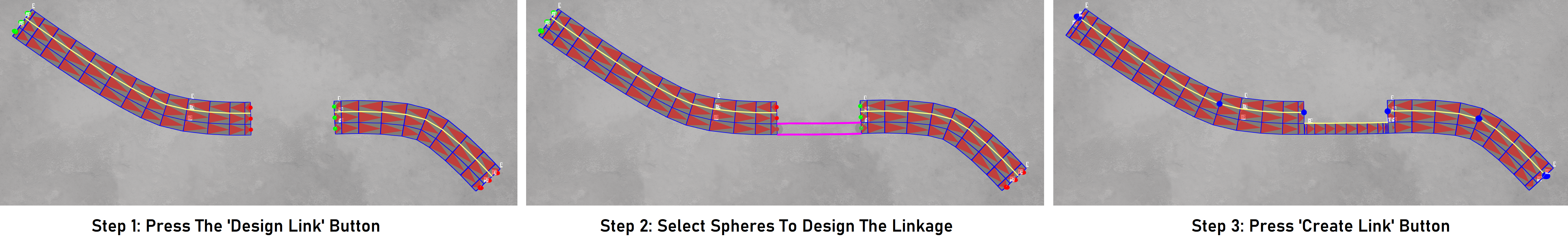
The following image demonstrates the steps required to create a linkage between two roads.
Note: the editing features available for link roads is limited compared to other roads. This is to prevent various undesirable behaviours.
Multi-Lane Linkage:
In a more complex example, we will join multiple lanes from one road to multiple lanes from a second road. This is done in a similar way to the simple case above, but there are some considerations which should be noted.
When selecting multiple lanes on the same road, they must be adjacent. That is to say that if we select lane 2, we must choose either lane 1 or lane 3 next (if they exist) - we cannot select lane 5 or lane -2. Bearing this in mind, and moving lane-by-lane, we can select a wide band of lanes from one road.
This is similar for the second road, and we also must remain careful with respect to the flow of the road (as we did in the simple case). Lanes can be added and removed from the candidate linkage, from both roads, and the linkage visualisation will update accordingly to show how the proposed linkage will appear.
Assuming the linkage is valid (incoming and outgoing directions match across the selected widths on both roads), then the ‘create link’ button will become available to the user, and it can be pushed to generate the wide link road.
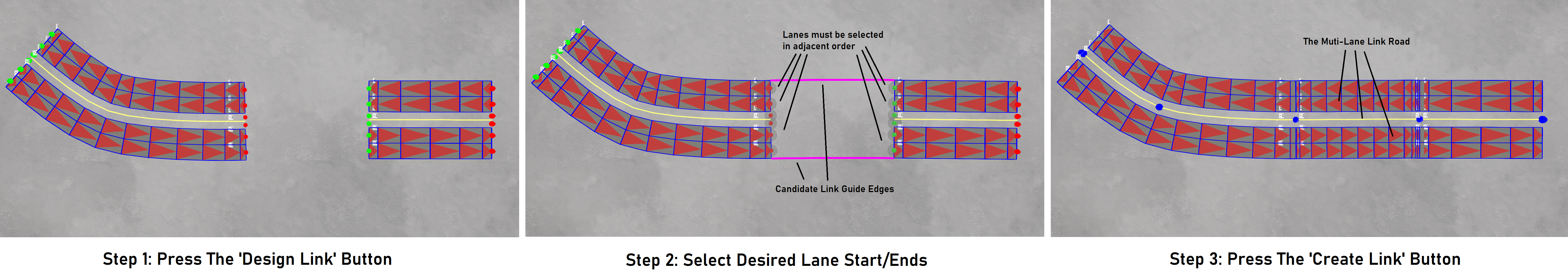
The process is illustrated in the image below.
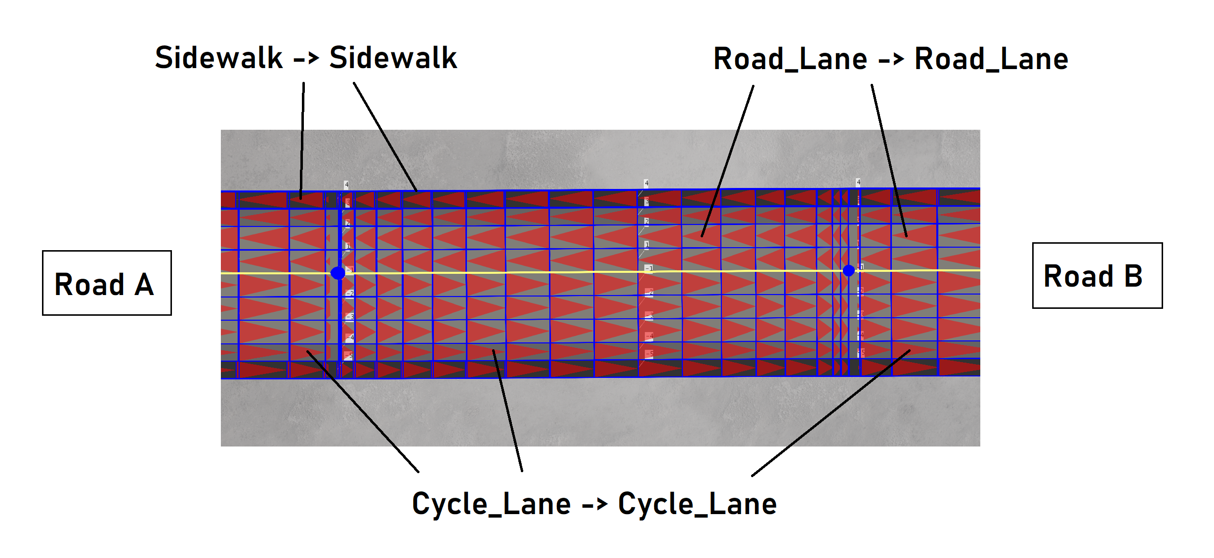
For a link to be valid, there is another condition which must be satisfied: lanes can only flow into lanes (in the second road) of the same type eg road_lane -> road_lane, cycle_lane -> cycle_lane, island -> island, sidewalk -> sidewalk, etc. We cannot, for example, connect a road_lane to a cycle_lane. The user should be aware of this condition, since if it is not satisfied, the ‘create link’ button shall not appear until it is resolved.
Note: lanes from both the left and right side of each road can be selected, as long as they are selected in an adjacent order (eg by selecting -2, then -1, then 1, then 2, etc).
Note: if the width of a lane has been collapsed (set to zero at the start/end point where the user is creating a linkage), then it cannot be selected. Usefully, this removes the adjacency condition described above, allowing the user to skip that collapsed lane when computing the proposed linkage. Care needs to be taken when widths are changed dramatically, as the linking tangents can appear to be dubious - we recommend to minimise the slope of changing widths near the start/end points of roads which are later to be joined.
Junctions:
Junctions and intersections can be designed by combining multiple lane linkages.
Sometimes this will involve overlapping linkages. However, the user should be carefully when joining lanes at different heights since the lanes could ‘cut through’ eachother. Consider the case of a junction where a slip road rises from a lower road to a higher overpass road. If this slip is to merge into a lane at the upper height, care must be taken. The user can experiment and use the editing tools to achieve a satisfactory roads layout, but should bear in mind that some linking cases will not appear realistic and/or be undriveable in practice.
Width/Height Interpolation:
When link roads are created, the width and relative height values for each lane are smoothly interpolated from one road to the other. This attempts to provide a smooth transition per-lane. The following image highlights this for lane widths.
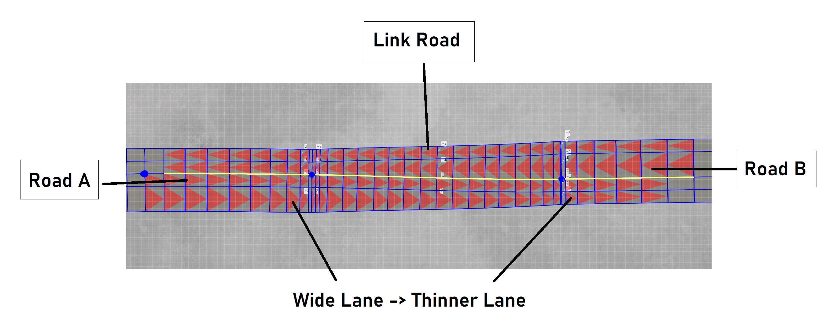
The user should be careful if, for example, a lane with a large width is linked to a lane of small width. This may produce unconvincing results. We recommend to minimise the transition gap or to increase the distance between the roads (thus increasing the link road distance) so as to give the interpolation more space with which to transition.
Note: If the width at the joining start/ends of the roads are suddenly different from neighbouring values, the start/end tangents of the road may become ambiguous. In such cases, when links are created, they may appear not to join at the correct angle. We recommend to minimuse the rate of change of the width near to any joining start/end of any road which is to be linked, in order to avoid this issue.
Lane Type Matching:
When linking between two roads, the lane type (road_lane, cycle_lane, sidewalk, island, etc) must match. Each lane type can only join to a lane on the other road of the same type. If this is not the case (ie the designed linkage is not valid), then the ‘Create Link’ button will not appear.
The following image shows an example of lane matching using a standard ‘urban’ lateral road profile contains sidewalks, cycle lanes and road lanes.