Jbeam Tips and Tricks
This is a collection of tips and tricks discovered over the years by the developers. Following them can improve the quality of your Jbeam structures. These are meant for experienced modders who already know how to make a full vehicle, however they can be useful for beginners as well.
IDE
This refers to the software you choose to edit your Jbeam files in, such as Visual Studio Code or Cursor .
Indentation using spaces
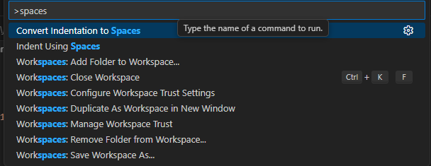
Consider using a setting, command or macro that makes it so the indentation in your Jbeam files is done with spaces rather than tabs. This way, the indentation will stay exactly the same if you or someone else happens to open the file via another editor.
Vertical selection
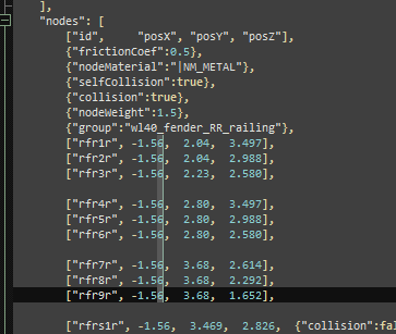
It is best to indent your Jbeam in a way that the node names and coordinates are aligned in columns.
This way, whenever you need to change a value in many rows at once, you can use vertical selection (SHIFT + ALT + LMB or use middle mouse button instead of left one in VS Code and related programs).
Batch replace in selection
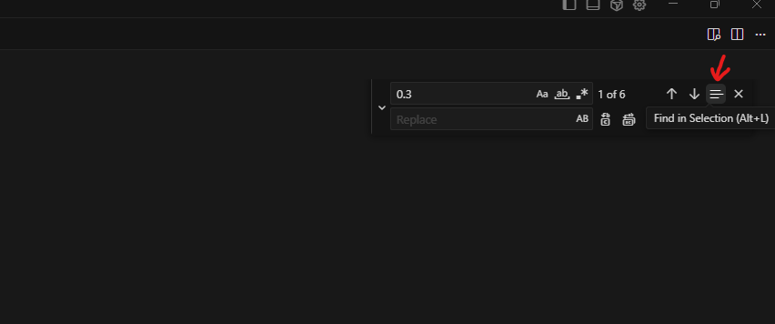
When doing a batch rename/replace job in a Jbeam file, always make sure to limit it to the currently selected lines, to prevent messing up the syntax in Jbeam modifiers.
Cursor AI
If you use Cursor instead of Visual Studio Code to edit your Jbeam files, you can get help from the built-in AI. While it cannot design Jbeam structures for you, it is useful for long, boring, precise tasks, such as tweaking the positions of many of slidenodes to align with their rails.
Nodes, Beams, Triangles
Here you will find some tips related to the structural pieces of Jbeam.
Jbeam collision system
Here’s all the information about Jbeam collision from various parts of the documentation, condensed into a single list. You can refer to it when debugging collision issues.
- There are 3 types of collision. Heightmap collision, static collision, and dynamic collision. They are all exclusive to nodes in Jbeam.
- Static collision has a bigger performance impact than heightmap collision.
- Heightmap and static collision is controlled by
staticCollisionparameter in Jbeam, which by default will be the same ascollisionparameter unless explicitly defined for a node. - Heightmap collision has some ‘depth’ that helps tires roll smoother.
- Dynamic collision has higher priority than static collision.
- Dynamic collision separates into
collision(inter-vehicle) andselfCollision(between parts of the same vehicle) in Jbeam. - If
collisionis false thenselfCollisionwill be disabled even if set to true. - If a node is
fixedthencollisionandselfCollisionare disabled butstaticCollisioncan still be enabled. - If a node is a standard or advanced
couplerthenselfCollisionis temporarily disabled on it while it’s coupled. SelfCollisionwon’t apply between a node and a triangle made of nodes with the samegroupas that node (in case of multiplegroupsit’s the first one). This can and should be abused if you want specific nodes and triangles to not collide but still generally wantselfCollisionthere.- Triangles have “thickness” of 2.5 cm, which is how far from the green side triangle surface a node can be before collision applies. In debug tools, this is visualised when on default settings the node and triangle are touching.
- Triangle thickness can be changed with
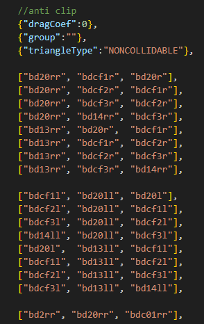
externalCollisionBiasparameter if you have clipping issues that can’t be fixed in other ways. - Triangles have not only collision, but also anticlip system. That decides on which side of the triangle a node will end up after collision.
NONCOLLIDABLEtriangles still have anticlip, but are way better for performance.- It’s important that each node with
selfCollisionhas at leastNONCOLLIDABLEtriangles on the surface that can collide with things the easiest. This is why exhaust pipes haveNONCOLLIDABLEtriangles for example.
BreakGroup as a table
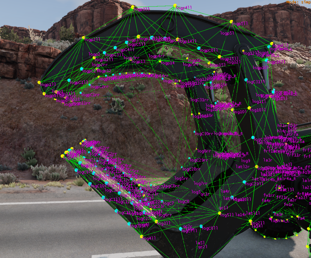
BreakGroup can be a table, and with breakGroupType set to 1, it means the beam will break when either of the 2 breakGroups is triggered.
This can help a lot with support beams. For example, if you have a front and rear door with support beams between them, and you want them to break when either door breaks off.
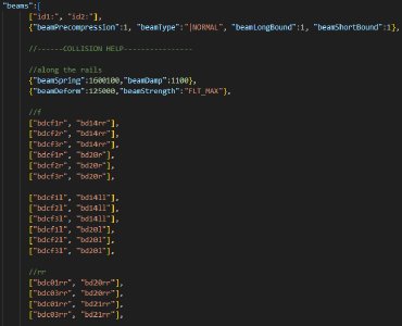
Breaking rails and torsionbars
Rails and torsionbars don’t support breakGroups the way you may expect them to. To properly break a link of a rail, you need to break the beam that goes between the nodes of the link. To break a torsionbar, you have to break a beam that goes between two of its consecutive nodes.
It is often the best to set up a dummy beam, with no spring or damp, max deform and strength, with disableMeshBreaking and disableTriangleBreaking properties, with the breakGoup (or multiple of them) you want to be linked to the rail/torsionbar, positioned between 2 of its nodes, and breakGroupType set to 1. This beam will exist purely to break the rail/torsionbar and won’t have any side effects.

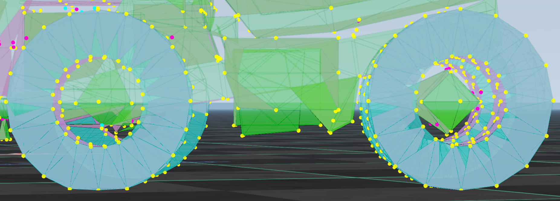
Collision slidenodes
Sometimes, you might want to increase the density of nodes along the edges of a structure, for example to prevent things from clipping into the edge when they fall directly on it. You can do it without messing up the deformation of the structure, using rails and slidenodes.
This is an algorithm of adding the collision slidenodes in a way that is optimal for deformation and performance:
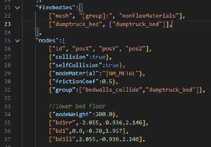
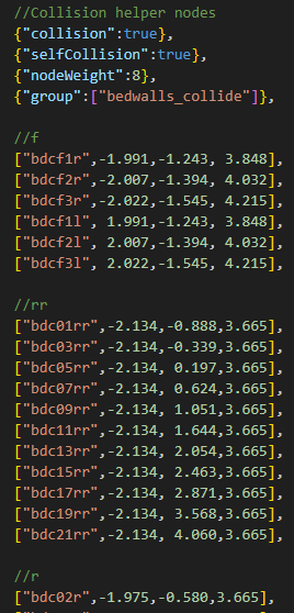
- Make all the nodes on the part have 2 groups. Group 1 for collision, group 2 being the same as on the mesh.
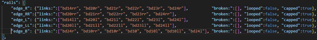
- Add rails between all the nodes on the edges where you want more collision points.
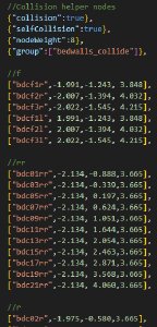
- Add nodes that will act as slidenodes on those rails. They should have selfCollision enabled, and should only belong to group 1. This way, they won’t collide with the triangles they are on, but will collide with other parts of the vehicle. If 2 edges are close to each other, stagger the nodes on them for better performance.
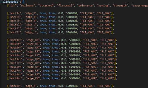
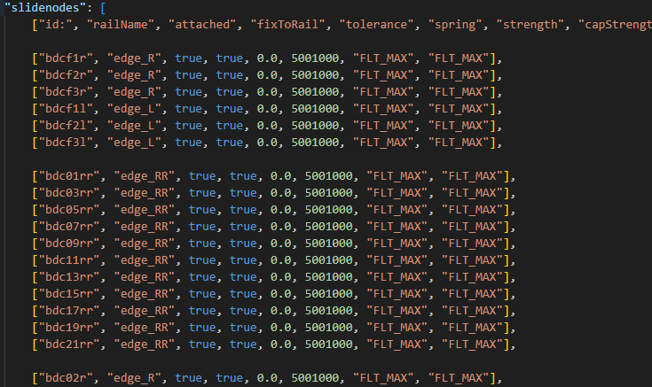
- Define the slidenodes on their rails. Now the collision nodes will be locked on their rails, but will still be able to slide along them.
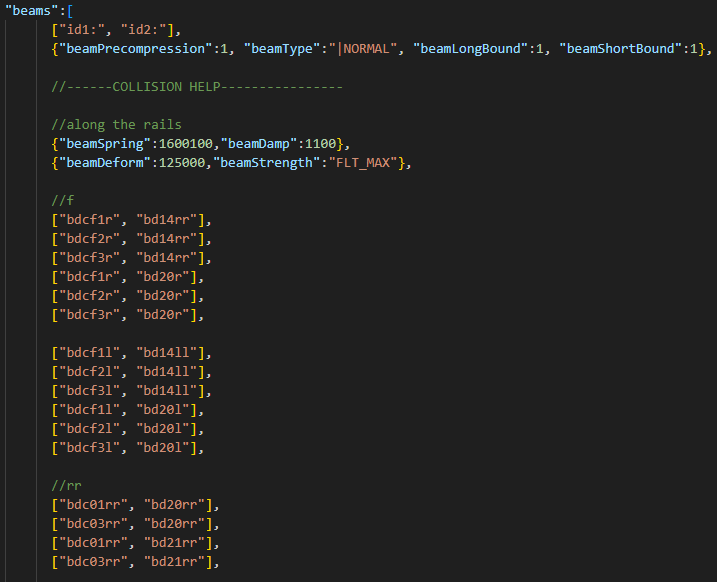
- Attach each node to the structural nodes along the rail in both directions by beams. Now the collision nodes are fully locked.
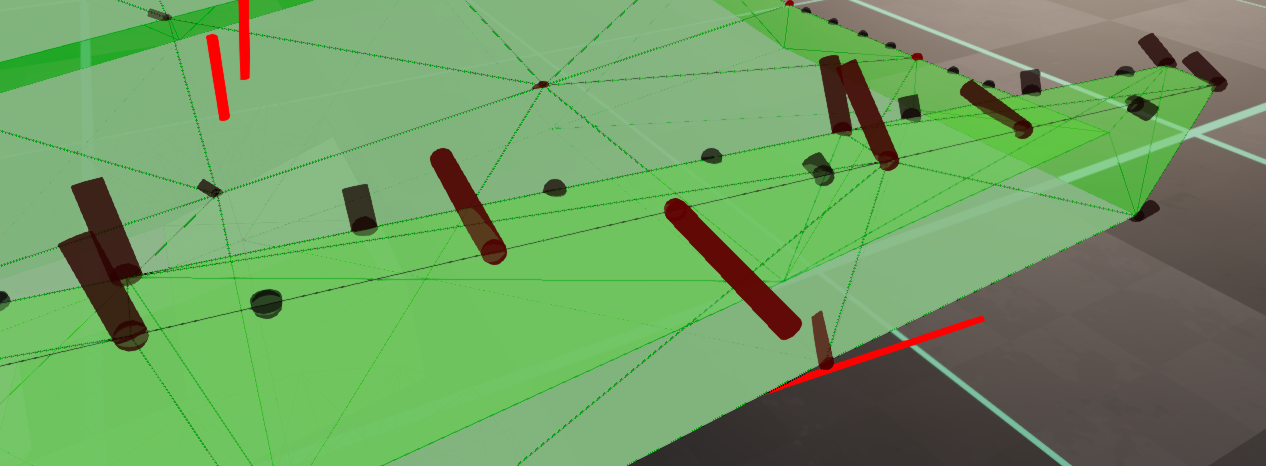
- The slidenodes are not stable yet because the rails lack damping. Test in which directions the collision nodes shake when pulled with nodegrabber. Use the node forces debug.

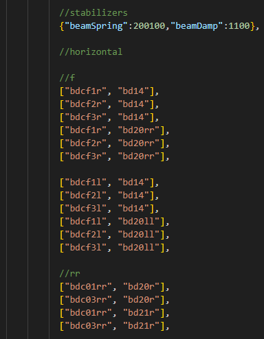
- Add beams in the direction of vibration, between the collision nodes an other structural nodes of the part. Repeat previous and this point until the shaking can’t be replicated anymore.
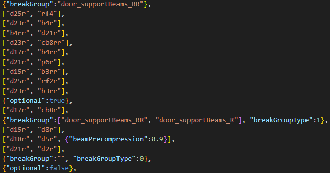
- Add
NONCOLLIDABLEtriangles on top of the triangles that are already in the part, between the collision slidenodes and the structural nodes, as if you were Jbeaming it normally without the triangles of the structural nodes existing. This way, the anticlip system will work for the collision slidenodes, preventing them from getting stuck, without the performance cost of adding more collidable triangles.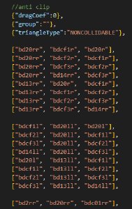 Adding said triangles is easier with the structural triangles temporarily removed, so you can see what you are doing with the debug visualization.


Flexbodies and Props
This section contains some tips about positioning visual vehicle parts in Jbeam.
Global arguments
For spotlight and pointlight props, it is usually better to use the baseTranslationGlobal optional argument instead of the default baseTranslation. Similarly, baseRotationGlobal instead of baseRotation. These use the same coordinate system as Blender, so you can line them up with the 3D model without any guesswork.
Example:
"props": [
  ["func", "mesh", "idRef:", "idX:", "idY:", "baseRotation", "rotation", "translation", "min", "max", "offset", "multiplier"],
  {
      "lightInnerAngle":0,
      "lightOuterAngle":120,
      "lightRange":8,
      "lightColor":{"r":255, "g":10, "b":0, "a":255},
      "lightAttenuation":{"x":0, "y":1, "z":1},
      "lightCastShadows":false,
      "flareName":"vehicleBrakeLightFlare",
      "flareScale":0.012,
      "lightBrightness":0.08,
  },
  ["brakelights", "SPOTLIGHT", "t4r", "t4", "t3l", {"x":0,"y":0,"z":0}, {"x":0,"y":0,"z":0}, {"x":0,"y":0,"z":0}, 0, 0, 0, 1,
  {"baseTranslationGlobal":{"x":-0.22, "y":2.44, "z":1.07},"baseRotationGlobal":{"x":0, "y":0, "z":180},"deformGroup":"reverselight_break"}],
  ["brakelights", "SPOTLIGHT", "t4r", "t4", "t3l", {"x":0,"y":0,"z":0}, {"x":0,"y":0,"z":0}, {"x":0,"y":0,"z":0}, 0, 0, 0, 1,
  {"baseTranslationGlobal":{"x":-0.13, "y":2.44, "z":1.07},"baseRotationGlobal":{"x":0, "y":0, "z":180},"deformGroup":"reverselight_break"}],
  ["brakelights", "SPOTLIGHT", "t4r", "t4", "t3l", {"x":0,"y":0,"z":0}, {"x":0,"y":0,"z":0}, {"x":0,"y":0,"z":0}, 0, 0, 0, 1,
  {"baseTranslationGlobal":{"x":-0.04, "y":2.44, "z":1.07},"baseRotationGlobal":{"x":0, "y":0, "z":180},"deformGroup":"reverselight_break"}],
  ["brakelights", "SPOTLIGHT", "t4r", "t4", "t3l", {"x":0,"y":0,"z":0}, {"x":0,"y":0,"z":0}, {"x":0,"y":0,"z":0}, 0, 0, 0, 1,
  {"baseTranslationGlobal":{"x": 0.04, "y":2.44, "z":1.07},"baseRotationGlobal":{"x":0, "y":0, "z":180},"deformGroup":"reverselight_break"}],
  ["brakelights", "SPOTLIGHT", "t4r", "t4", "t3l", {"x":0,"y":0,"z":0}, {"x":0,"y":0,"z":0}, {"x":0,"y":0,"z":0}, 0, 0, 0, 1,
  {"baseTranslationGlobal":{"x": 0.13, "y":2.44, "z":1.07},"baseRotationGlobal":{"x":0, "y":0, "z":180},"deformGroup":"reverselight_break"}],
  ["brakelights", "SPOTLIGHT", "t4r", "t4", "t3l", {"x":0,"y":0,"z":0}, {"x":0,"y":0,"z":0}, {"x":0,"y":0,"z":0}, 0, 0, 0, 1,
  {"baseTranslationGlobal":{"x": 0.22, "y":2.44, "z":1.07},"baseRotationGlobal":{"x":0, "y":0, "z":180},"deformGroup":"reverselight_break"}],
],
Flexbody rotation setup in Blender
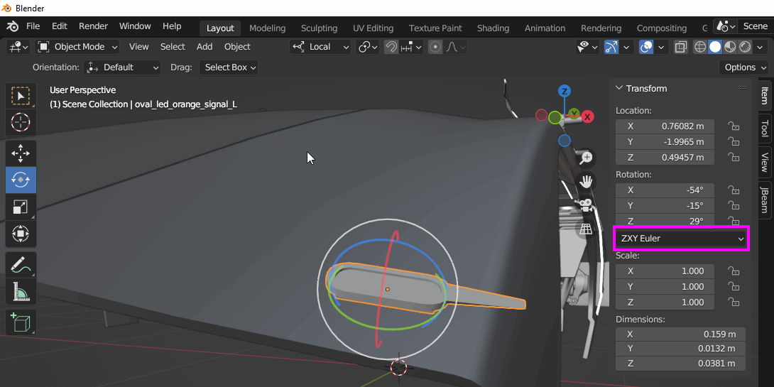
When using generic common flexbodies, such as offroad lights, you often need to rotate them by several axis at once to align with the rest of the 3D model.
You can set up the rotation in Blender. Import the part you want to use, position it, set the rotation system as ZXY Euler, rotate the mesh, and copypaste the result to Jbeam.
Troubleshooting
This section is for finding and fixing common issues.
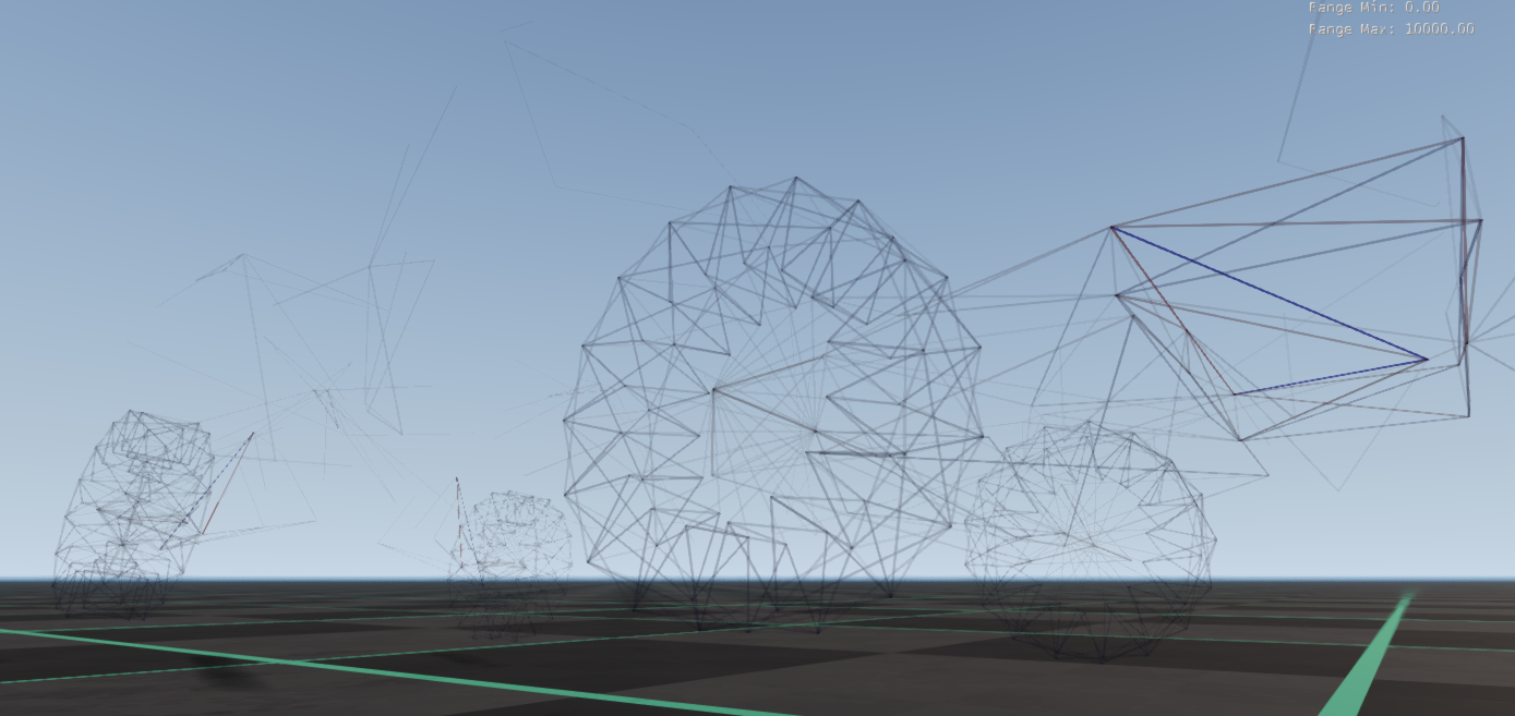
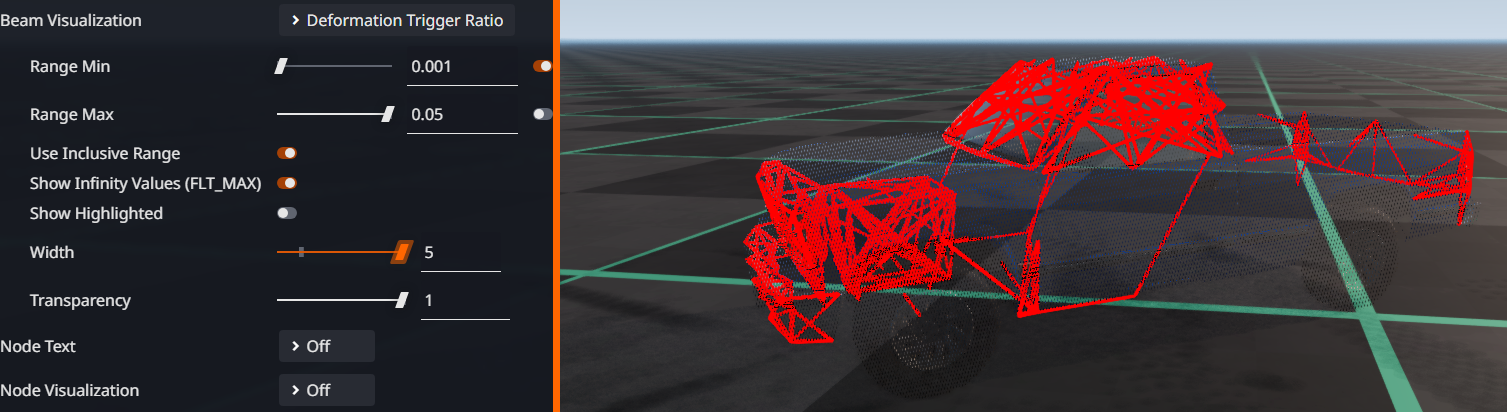
Checking for deformed beams
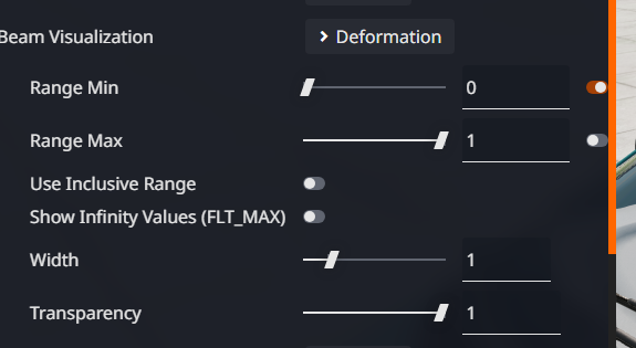
It is often useful to check for any beams that have deformed at all. To do this, in the Debug tab in the Vehicle Configurator:
- set the Beam Visualization mode to
Deformation - untick the switch next to the
Range Maxinput - uncheck
Use Inclusive Rangebelow - leave the other settings at default.
This will highlight all deformed beams and print the information about them in console.
Stress checking
Excessive beam stress is an early sign of structural issues, such as node-triangle clipping, misaligned slidenodes, or beam precompression issues. To properly check for the stress levels on a car:
- Set gravity to zero in the Environment menu.
- After the car has risen from the ground, reload it with CTRL + R to zero out the inertia.
- Turn the engine off via the UI or the V key, to relax the drivetrain and hydraulics.
- Using the Debug tab in the Vehicle Configurator, or CTRL + NUMPADMINUS combo, reduce the mesh visibility of the car.
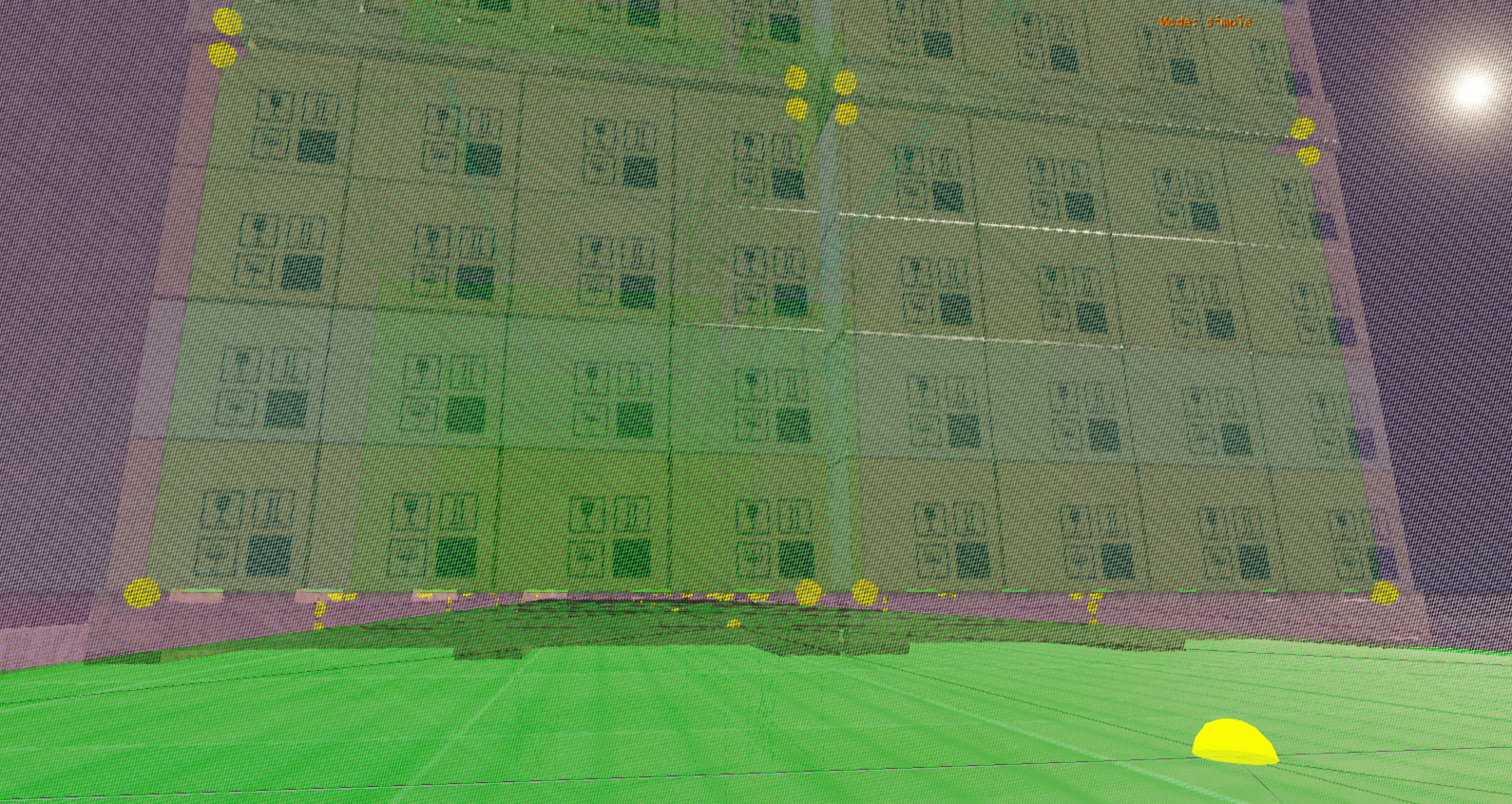
- Set the Beam Visualization mode to “Stress” via the debug tab, or by cycling CTRL + B.
- You might want to wait for a few seconds to make sure everything is stable.
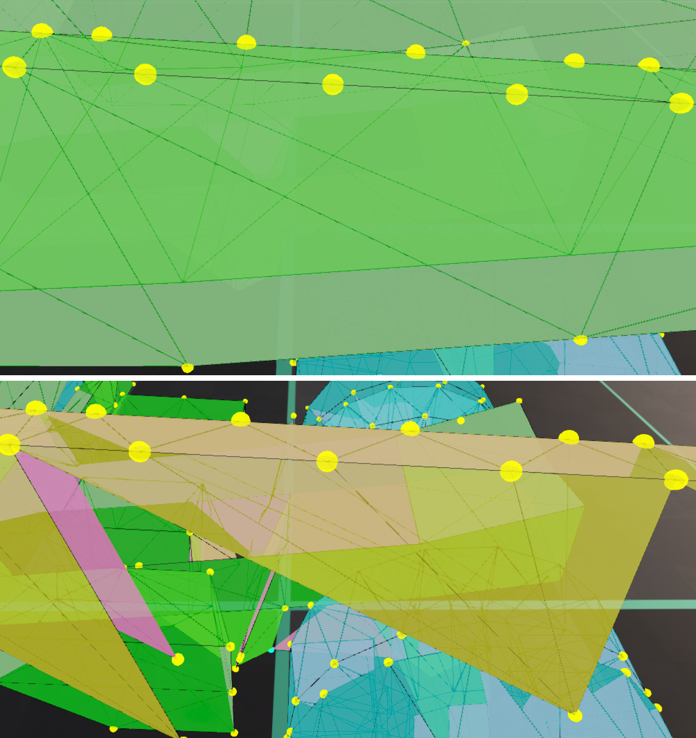
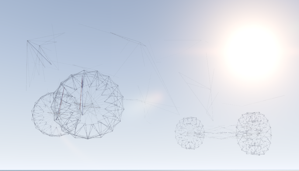
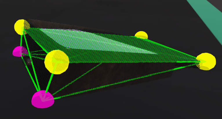
On a stable Jbeam structure, the result will look similar to this. There should be few stressed beams, and they will be parts of suspension, tires, and openable panel latches.
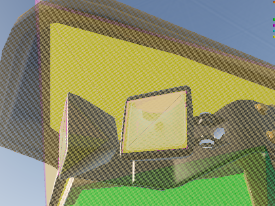
On an unstable structure, you will clearly see some areas having bigger stress than others. This is a sign that something around these areas needs fixing. You can turn on the node names visualization to see which exact node is problematic. Check for:
- nodes colliding with triangles on spawn (tip: use the Node Triangle Self Collision Detector )
- slidenodes not being correctly aligned with their rails in the Jbeam file
- leaking beamPrecompression modifiers.
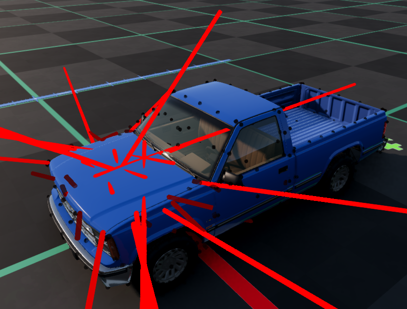
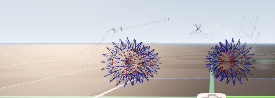
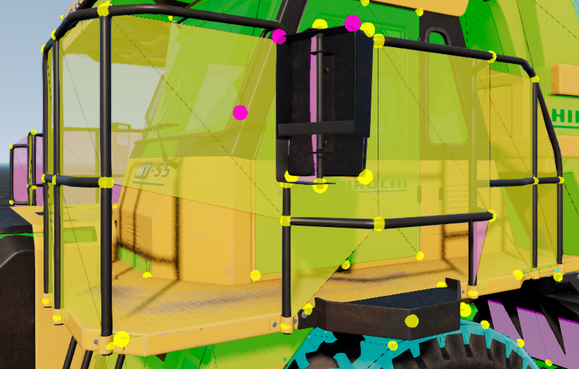
Unstable vibrations
When a flexbody is vibrating on spawn, it’s usually a sign of too high spring and/or damp values per node weight somewhere. To narrow down the specific spot where the issue is happening, you can use node force debug visualization. The areas with most/biggest unstable forces are the most likely to be problematic. Stable forces (those that aren’t rapidly changing the size/direction) can be ignored as they are caused by couplers.
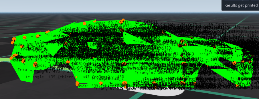
Note that while it is possible to use beam stress debug and node forces debug interchangably in most cases, they will provide very different results for very heavy and stiff vehicles, as the forces scale with the node weight, unlike the stress.
On a heavy and stiff vehicle, using node forces debug can produce lots of false positives around heavy, load bearing nodes.
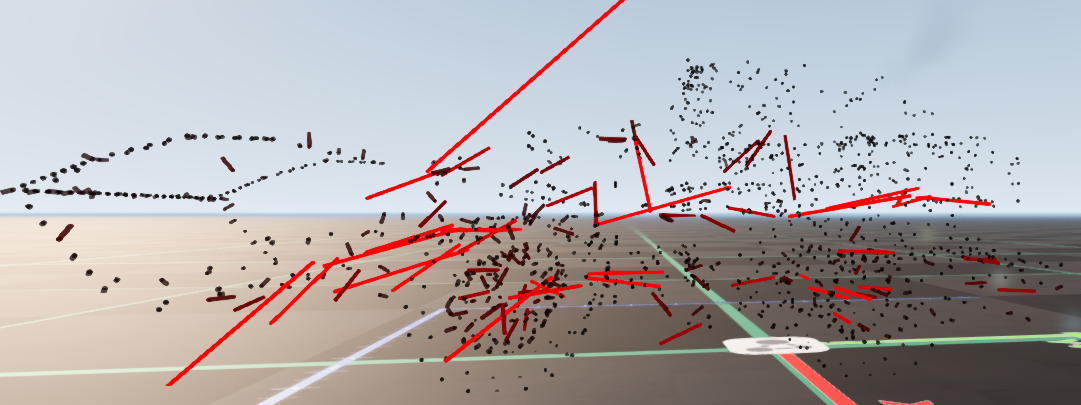
Meanwhile, beam stress debug will behave closer to how it does on a normal vehicle - the difference being that naturally stressed beams, such as those on tires, will appear a lot more pronounced, making it harder to notice actual issues.
Therefore, on such vehicles it is best to check both modes to make sure there aren’t any actual issues.
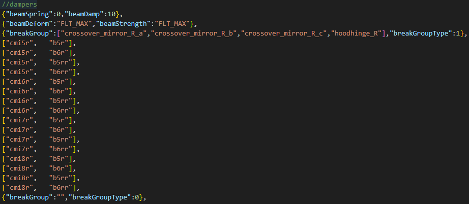
Long structure wobble
Some long structures with most of the mass at the end, like a school bus crossover mirror with a long arm, have inherent wobbling issues that are hard to fix. This is a tip how to combat that:
- Add beams purely for damping, going to some other part that isn’t directly connected to your part, so that you have more leverage.
- Set up a breakGroup for those beams as a table: include every breakGroup of the chain of parts between the 2 nodes of the beam, so the damping beams break when any link of the chain gets destroyed.
- Set breakGroupType to 1, so that breaking off your part doesn’t affect the other parts. Also set beamStrength to max so the beams don’t break from excessive forces.
Performance optimization
Refer to this section if your Jbeam has performance issues on the CPU side.
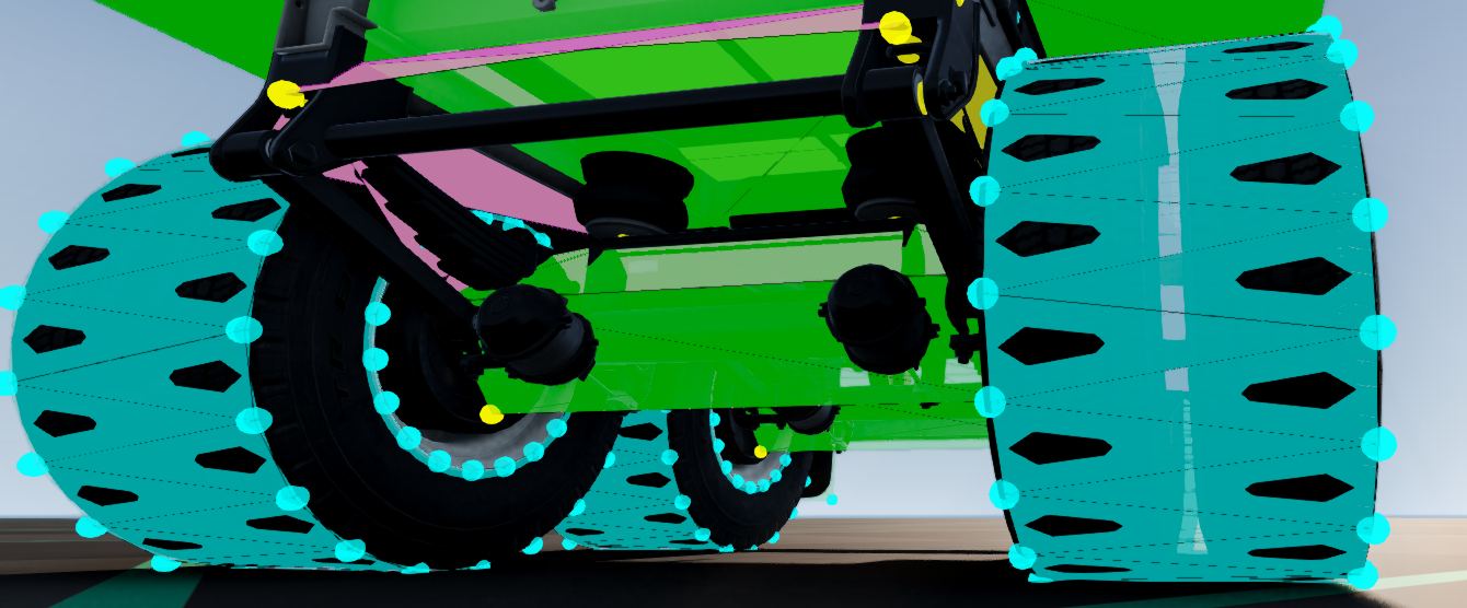
Large tires
Large tires need a balance between having good enough collision to be able to drive over a vehicle/prop without clipping, and having relatively good CPU performance, as they can easily end up being the most performance intensive part of the entire car. There are many tire parameters to play around with to achieve a good balance, for example:
selfCollision, if we are fine with the wheels not colliding with the rest of the vehiclenumRaysfor the node density on the tire. Less rays means better performance, but higher rolling resistance and chance of clippingwheelAnglefor dually tires - with the right setting,numRayscan be loweredtriangleCollision- should be enabled when your tire is big enough to drive over another vehicle, but it’s very costlyhubSide1TriangleCollision,hubSide2TriangleCollision- should be disabled if on your vehicle the tire is more likely to get hit than the wheel; can also be enabled on 1 side only if needed, and/or for inner dually tiresenableTireLbeams- disabling it can help with performance if the vehicle has many wheels, but it will increase rolling resistance in a hard to conquer way
A good compromise is often selfCollision enabled, numRays lower on dually wheels, hubSide1TriangleCollision and hubSide2TriangleCollision off, other parameters adjusted specifically for the vehicle.
Dually wheels can also be built as a single wide wheel. This offers a massive performance gain, but has many disadvantages, so it should only be done on truck trailers, where the wheels aren’t powered and don’t directly collide with anything in front of them.
Triangle sleep mode
If a triangle has no nodes that can potentially collide with it (no selfCollision, different group, no coupler, etc.) within 10cm of either side, it will enter “sleep mode”, improving performance a bit. The gain can be big with lots of triangles like that.
This is good to keep in mind when optimizing big enclosed structures like upfit/trailer interiors. For example, on the dry van trailer, the loads hover above the floor to make use of this.
Noncollidable triangles
Tiny structures with dense nodes, like offroad lights, should ideally use NONCOLLIDABLE triangles instead of NORMALTYPE ones.
This is because a collidable triangle has no extra performance impact when it has no nodes within 50cm of its surface, but each node within this range adds extra performance impact. It can get pretty bad with lots of nodes per triangle, so in dense areas, triangles should be NONCOLLIDABLE.
NONCOLLIDABLE triangles can also be used on parts like railings, where you have big collision gaps, so that collision is done via nodes only, and the triangles exist just for anticlip.
Jbeam clipping
If a node is clipping with a triangle while driving (is within 2.5cm of it and collides with it), it will constantly generate collision events. If you have many nodes like that on the car, it will start getting hard on performance.
Generally the minimum distance between nodes and triangles should be 3cm, maybe 3.5 for particularly flexible parts, to have some extra margin of safety. Use the Node Triangle Self Collision Detector
to find nodes like that.
DeformGroups
When using deformGroups, remember that deformationTriggerRatio is the performance intensive property, not deformGroup itself. Always make sure you aren’t leaking the deformationTriggerRatio property anywhere! You can check it via the beam debug modes.
 Keep in mind that
 deformGroups will also trigger when beams break, not just when they reach the ratio. So you can set up deformGroups to activate at beam breaking where possible, and that will be easier on performance.
Ground collision
Static collision has a bigger performance impact for map objects than for heightmap collision. So for a vehicle that will be often driving over map assets like rocks rather than a normal decal road, it is more important to have less nodes on the bottom. This is why skidplates on rock crawlers don’t have too big node density.

Separate static and dynamic collision
Some structures are too thick for flat plane Jbeam, but too thin to justify full three-dimensional dynamic collision for performance reasons (see Noncollidable Triangles above), for example flat rectangular mirrors on a truck. If you want them to have accurate collision with the ground but you are not concerned with dynamic collision, you can have some nodes with collision and selfCollision disabled, but staticCollision enabled, and no triangles going to them. This will help performance, especially if they are close to triangles of another part.
Was this article helpful?