Elements
Nodes
Nodes are the basic building stones of your flowgraph.
Every node provides some kind of functionality, that is based around the concept of processing input and giving output.
A good example of this, is the “Expression” node:
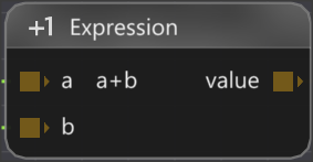
It receives the values “a” and “b” on its input pins, processes them and gives back “value” on its output pin.
With the wide variety of nodes provided by Flowgraph, you can build complex scenarios to bring interaction to your levels.
There are also nodes that are only used for putting out values without having any input pins:
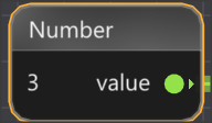
This “Number” node provides a value, that can be set in internally and is not provided from an input pin.
On the other hand there are nodes that only take in data through input pins and process it, but do not provide any output pins. They could for example be storing the input in a variable or cause a reaction in the game world.
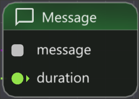
This “Message” node for example takes in a message and a duration and then displays this message in the ingame UI to the player. It does not provide any kind of output.
Most nodes require “flow” to function. You can learn more about flow here
.
Creating Nodes
There are multiple ways to add nodes to you graph.
The simplest way is pressing Right Click on a free space in the graph and selecting the node you want from the context menu.

Another way to add a new node is by pressing Left Click and dragging a link from a pin to a free space in the graph. This will directly connect the newly created node to the pin.
At last you can also create nodes through the “Node Library” window. You can learn more about it on the Windows page.
Removing Nodes
You can remove nodes by either:
- Selecting them and pressing the Delete key.
- Pressing Right Click on them and selecting Delete in the menu.
Node Behaviours
The different nodes of Flowgraph provide a wide variety of different functionalities, that you can use for your project. To give you a better understanding on how to interact with a node and how it will behave we introduced Node Behaviours.
You can see the behaviours of a node as icons in the top right corner of the title bar. When hovering the node you see a detailed explanation of what these behaviours mean:
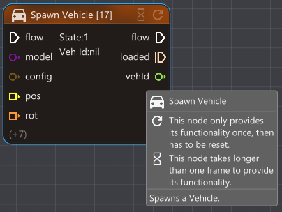
The following node behaviours currently exist in Flowgraph:
- Once

This node only provides its functionality once, then has to be reset. - Duration

This node takes longer than one frame to provide its functionality. - Simple

This node does not require flow to function.
Dynamic Nodes
The standard behaviour for nodes in Flowgraph is that they provide their functionality repeatedly as long as they are receiving flow. But we have already seen that for some nodes it makes sense, to only function once, like the “Spawn Vehicle” node. We wouldn’t want it to spawn a vehicle on every frame. We can recognize these nodes by their flag.
Between “repeat” and “once” behaviour there are nodes, that in different use cases, could use both functionalities. Lets look at the “Set Gravity” node as an example.
1. “Repeat” Use-case

In this situation we are setting the gravity on every frame, as long as the node is receiving flow. This could be useful in a scenario, where we are gradually changing the value input and want the gravity to be constantly updated.
2. “Once” Use-case

In this situation we are setting the gravity only once, even if there is constant flow incoming. After that the node has to be reset by using the “reset” pin to work again. This can be useful in scenarios, where the player reaches a new game state and gravity has to be adjusted just once.
In earlier versions of Flowgraph, if you wanted the “Once” behaviour, you would have to add an additional “Once” node before the node, so the flow gets converted to impulse.
To give you more control over how you want to use your nodes, we added “Dynamic” nodes. These nodes are able to switch between the “Repeat” and the “Once” behaviour depending on what you need.
To switch behaviours you can simply select the node and view it in the “Properties” window.
Here you can see a Set Once or Set Repeat button that will dynamically change the behaviour of the node.
Pins
Pins define the input and output of a node.
The pins on the left side of a node are the input pins, while the pins on the right side are the output pins. To bring interaction and flow into your flowgraph, you can connect the input and output pins of different nodes with each other to create so called Links. You can read more about them below.
To define what kind of input and output a node has, each pin has a type:


With these types we can make sure, that a “number” input pin can only receive a number from a “number” output pin and any other pin won’t be able to create a link to it.
If you are unsure about the functionality of a certain pin, you can always hover over it to see the tooltips given by the node’s creator.
Pin Visibility
Since there are many situations in which you do not need all pins in a node, it can be useful to hide pins that are unnecessary in the current situation.
We can achieve this by selecting a node and viewing it in the “Properties” window. Here you can toggle its visibility with the  icon.
icon.
Hardcoded Pins
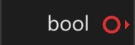
Another common situation is also that we want a constant input value for a pin, that does not need to be controlled by another pin. For example a message string, that is always the same “Hello World!”. To achieve this we can use so called “hardcoded” pins.
You can turn a normal pin into a hardcoded pin, by viewing the node it belongs to in the “Properties” window. Clicking on the pin symbol of the pin, will cause it to turn into a  symbol.
Now you can modify the value of this pin directly instead of giving it an input from another pin.

Links
Links define the flow of your flowgraph by connecting the pins of different nodes with each other.

When you create a link, you define that the output pin it is connected to will receive its input values from the input node the link is connected to.
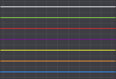
A link can only be created between two pins, if they have the fitting type. Depending on the type of the nodes the link will have a different coloration:
Creating Links
Links can be created in many different ways:
-
Pressing Left Click on a pin and dragging the link to another pin. You can only connect input to output pins:
-
Pressing Left Click on a pin, dragging the link to a free space in the graph and selecting a node to create. This will automatically create a link between the pin and the new node. You are only able to select nodes, that have an appropriate pin for the type of link you are creating:
-
Holding Ctrl, selecting two nodes and pressing C. This will automatically connect all similar pins with each other.
Removing Links
Links can be removed in many different ways:
-
The simplest way to remove a link is by selecting it and pressing Delete.
-
You can also remove a link by pressing Right Click on it and selecting Delete in the menu.
-
You can remove all links that are attached to a node by selecting that node and pressing X.

-
If you hold Ctrl and select multiple nodes, pressing X once will remove all links that are not between these nodes and pressing X a second time will remove all links inside that group of nodes.

-
You can of course also remove a link, by simply deleting one of the nodes, it is attached to.
Hiding Links
To improve the readability of your flowgraph, you are able to hide links.
This can be achieved in multiple ways:
-
Press Right Click on the link and select Hide Link in the menu.
-
Press H while one or multiple links are selected.
-
Press H while one or multiple nodes are selected. This will hide all links connected to the nodes.
There are also multiple ways to unhide links again:
-
If you just hid the link, you can press H again.
-
Selecting a node, will make the “ghost” of the link appear. Selecting this ghost will unhide it.

-
Pressing Ctrl+H while one or multiple nodes are selected. This will unhide all connected links.
Graphs
Graphs are the containers of your Flowgraph project.
Your project is made up out of different types of graphs, that together create the logic of your project. The best reason for having multiple graphs is increasing the readability of your project. Instead of having the whole project in one large graph, you can spread it out over many graphs, each with their own functionality.
Let’s take a look at the different types of graphs that exist in Flowgraph.
Flowgraphs
Flowgraphs are the most basic type of graphs in Flowgraph.
An active flowgraph will put out flow through its “on Update” node. This flow can activate other nodes and therefore create functionality within the flowgraph. The “On Update” node has 3 flow output pins:
- enterState:
Puts out flow once, when the graph is activated. This is useful for initializing the graph or general startup behaviour. - flow:
Puts out flow every frame. Since many nodes need constant flow to function, this will give power to the main part of your flowgraph. - exitState:
Puts out flow once, when the graph is exited. This is useful for cleanup tasks before entering the next flowgraph. The exitState is triggered, when the “Transition” node is used to leave the graph.
Stategraph
Every Flowgraph project has atleast one stategraph.
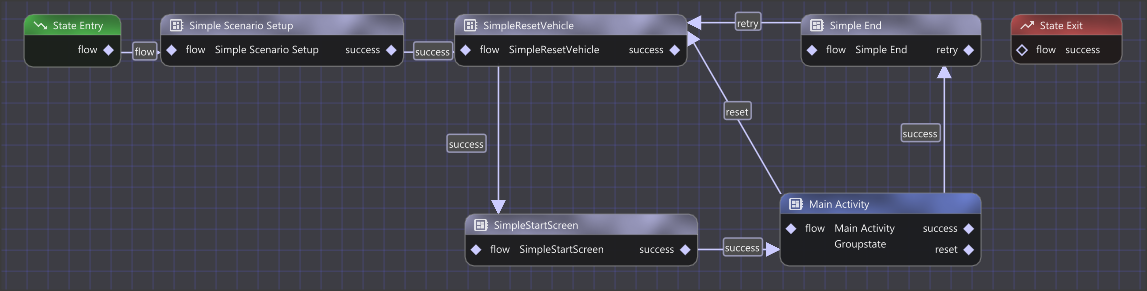
A stategraph does not have flow like a flowgraph, but only consists of states, that are either active or inactive. The “State Entry” node serves as the starting point for a stategraph.
Multiple states can be active at the same time and all of them will be come inactive once the “State Exit” is triggered.
A state can be one of two things:
- Flowgraph
When the flowgraph is activated, its “On Update” node will start putting out flow. - Groupstate
A groupstate behaves just like a stategraph and when activated, it will start at its “State Entry” node.
This allows for more clarity by for example grouping all the main activities of your project into one groupstate.
A state transition is either triggered by a “Transition” node in a flowgraph or by a “State Exit” node in a groupstate.
States can have different output pins for transitioning. This can be useful to differentiate between the different reasons for a transition, like a success or a failure. You can modify these output pins of a state by selecting it and viewing it in the “Properties” window.
You can then modify the transition that should trigger inside the “Transition” or the “State Exit” node.
Transition Stack
In many situations you want to communicate a value between states all within the same frame.
This can be achieved by using the “Transition Stack”. The transition stack is passed onto subsequent states and contains values indexed by their name.
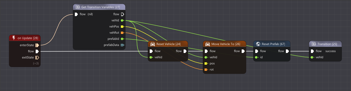
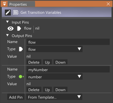
You can add a value to the stack by using the “Transition” node. In the “Properties” window for the node you can add or remove transition variables.
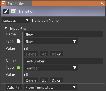
These variables can be accessed in later states by the use of the “Get Transition Variables” node.
Because values on the transition stack are indexed by their name, the string for storing and retrieving the transition variable has to be identical.
Should an already existing variable be set again, its old value will be overwritten.
Was this article helpful?