Basic Car Tutorial - Autobello Kit Car
Introduction
The goal of this guide is to show you the basics of jbeaming, while making a fully drivable car in beamNG.
Content covered by this guide
This guide will show you how to make a simple box style chassis, which works for race cars and simpler vehicles.
It will also show you how to attach various components to the chassis and tune them for maximum rigidity.
And finally, it will show you how to jbeam additional panels, including flat panels like a hood.
Prior knowledge required
This guide assumes you have some basic level of modeling knowledge, and have the ability to model a simple race car body. The included template includes the suspension and drivetrain components, however you will need to model your own chassis and body.
The project
One of the best way to introduce yourself to jbeaming is to create a simple tube chassis car using suspension and drivetrain from a vanilla vehicle.
This allows you to have a driving vehicle without having to delve into the more complicated aspects of building a powertrain and suspension from scratch.
Suspension especially is easy to get wrong, resulting in handling issues. Suspension involves more advanced jbeam notions, and also takes into consideration IRL suspension design parameters, so there is a lot to learn and a lot that can go wrong. This is fine if you already have a semi-decent understanding of jbeam but it can be frustrating for a beginner and result in a vehicle with poor handling.
As for the choice of a tubular chassis, it’s mainly because they tend to be fairly evenly rigid, meaning they can be jbeamed as a simple 3 node wide box structure. We will go over that later.
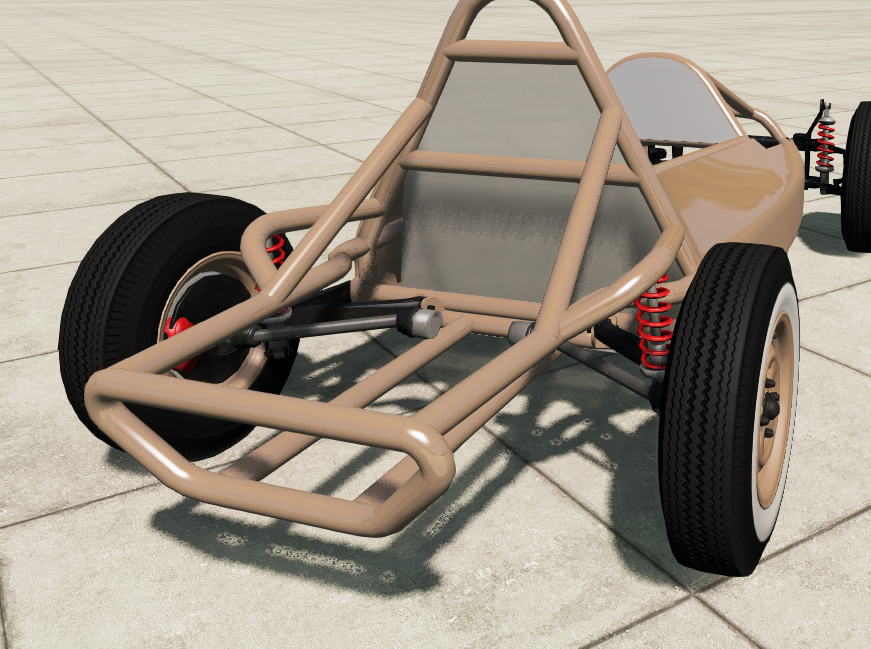
This brings us to the project, which is to create a kit car using the suspension and driveline from the Autobello. This type of configuration is used for a bunch of different kit cars, including buggies, various replicas of other cars, etc. It’s also a very common configuration in older racing series like Formula Vee, and many desert racing series, as an entry level category.
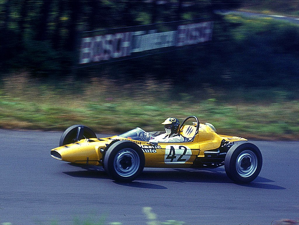 Olympic Formula Vee racing at Nürburgring in 1969 - By Lothar Spurzem - CC BY-SA 2.0 de
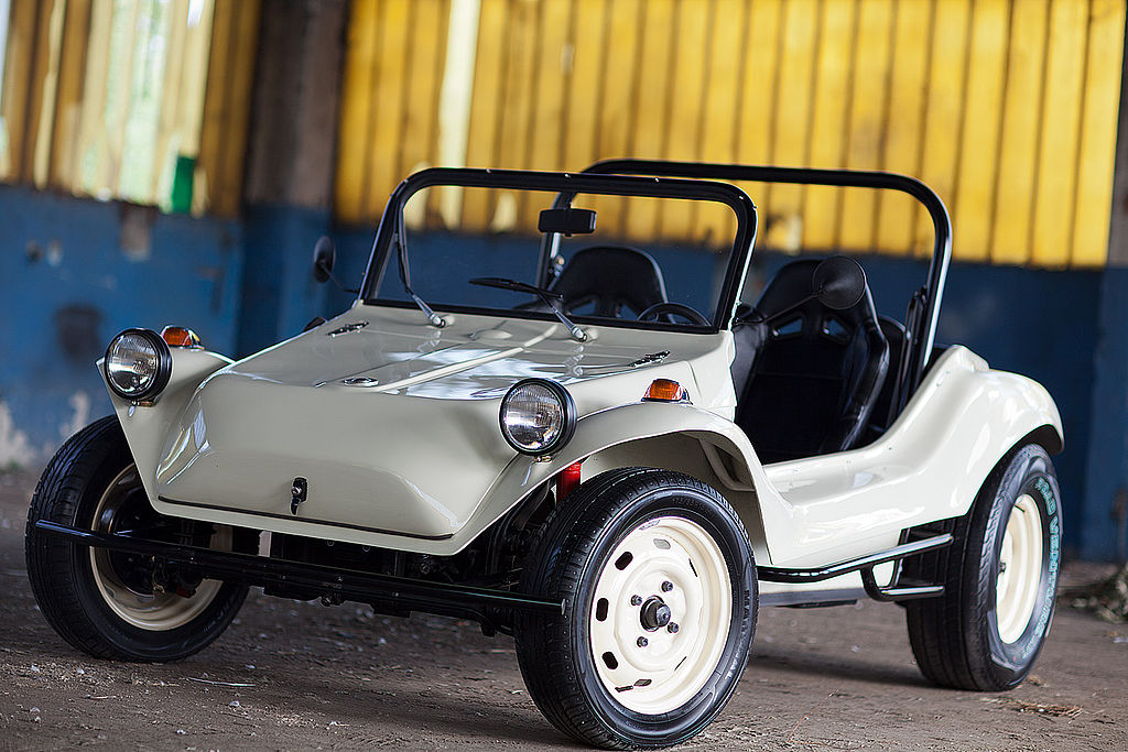 Ruska Buggy B1 Modified - By RuskaBuggy - CC-BY-SA-3.0
This guide is meant to be fairly generic and help learn the workflow of making jbeam. Any vehicle that uses VW style suspension and drivetrain can be replicated with this guide, as long as you’re fine with very basic deformation.
Make sure to keep your project simple at first to keep the project doable within a decently short time frame. Being able to drive you mod is great for motivation, and nothing keeps you from adding more things to the project after finishing this tutorial.
The template
The tutorial is built around the use of a template. It contains all the base jbeam parts you need, including the suspension, engine, and a template for the chassis and panels.
Setting up the files
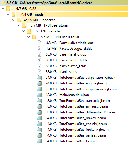
The first step is to create a new folder so you can start building the car in beamNG. Let’s start by creating a new folder in : %localappdata%\BeamNG.drive\currentVersion\mods\unpacked currentversion is the version number of the latest full version of the game, so for 0.22.1.0 you would go in : %localappdata%\BeamNG.drive\0.22\mods\unpacked. You might need to create the unpacked folder.
This new folder will be the root folder of the mod. It should have a name that’s descriptive and unique, as it needs to not be shared with any other mod on the repo to avoid conflicts. Adding your username to the folder’s name is heavily recommended. Inside that folder you will need a “vehicles” folder, which BeamNG will identify as containing vehicles or props. Then within that folder, create another folder with the same name as the first one, which will contain all the vehicle’s files. The folder structure should look like this.
You can now drag over all the tutorial files, along with your .dae model file.
Choosing between offroad and onroad parts
To allow for a bit more freedom when making a vehicle using the tutorial, I’ve included a set of offroad components in case you want to make a more offroad oriented vehicle. There are the same as the vanilla Autobello’s offroad suspension. To use these, simply copy over the jbeam files and the DAE file from the “OPTION OFFROAD” folder, and paste them in the folder you’ve just created, replacing the files that are included in the base template. As for the template blend file, use the file in the “OPTION OFFROAD” folder instead of the file in the root of the tutorial template.
Modelling
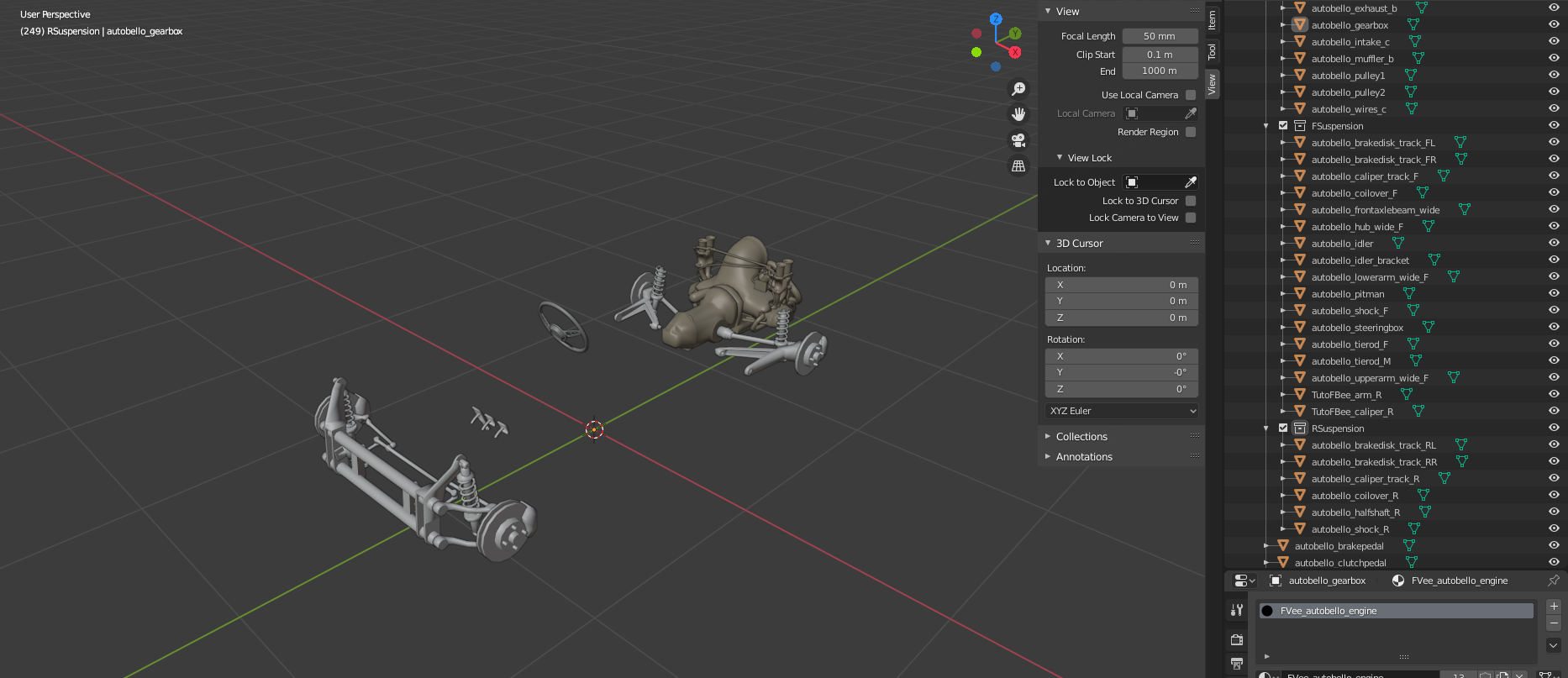
The first step of making any mod in BeamNG is to make a model for it. The vehicle template includes a Blender file with all the suspension and drivetrain components to make it easier for you, along with some basic materials. However you will still need to model your own chassis and body. For more info about making car models for beamNG, see the modelling guidelines page .
The model’s orientation should follow the game’s coordinates system: positive X = left, positive Y = back, and positive Z = up.
For its position relative to Blender’s zero point, the best practice is for it to be exactly centered on the X axis and roughly centered on the Y axis, and slightly above the Z axis center, for all Z coordinates to be positive if possible.
Template
The model includes renamed autobello materials, along with 5 basic materials which should simplify your job if you’re inexperienced. Those materials are also defined in the included main.materials.json file.
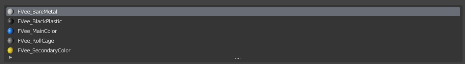
- Baremetal is a shiny light gray material
- Blackplastic is a matte black material
- The other three represent the 3 materials available in the color selector.
All the materials are single color textures with no normal map, which should be enough to get you started.
Basics of jbeam, and creating the chassis jbeam
Jbeam files
One of the things you might notice in the included package is numerous “.jbeam” files. These are the files that define your vehicle, including the physical structure, the various components, etc. When the game loads your vehicle, it will load all of these files, so you can split up your vehicles into as many files as you want. The general rule is that a file should only contain parts related to each other, making it easier to find components when it comes to fine-tuning and debugging. As with anything in the creation of mods, you can look at vanilla vehicles for inspiration.
Useful links
Here are a few links that help explain some of the basics you need to understand to build a car in beamNG.
For syntax, the main things to remember is that jbeam is set-up as tables with headers, and that brackets are used to define the various levels of tables. Missing brackets and headers are common issues that could cause a vehicle to not load.
General guidelines for jbeam design
The general rule with jbeam shape is that it only needs to follow the shape of the base model well enough to allow for decent collisions and deformations.
This means the jbeam is often way less accurate than some people think it needs to be. Here is the Blackpool Superlite as an example.
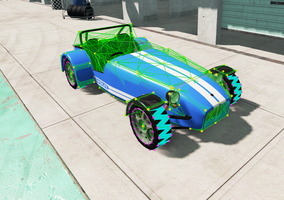
You can see the jbeam is a fairly simple 3 node wide box structures that mostly follows the body shape. While this does create some inaccuracies, it’s close enough to not be a problem in practice, while allowing for a simpler jbeam structure that’s easier to tune.
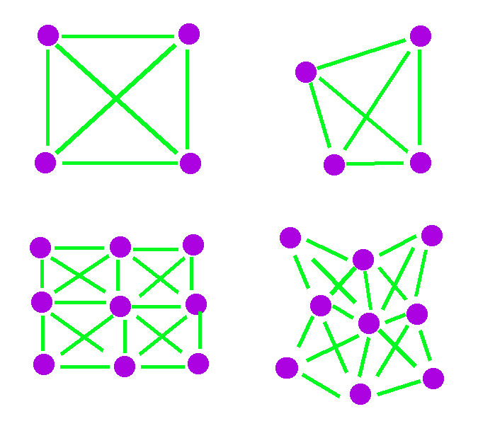
Jbeam density is a bit of a balancing act between having enough nodes to allow things to properly bend and deform, without having so many nodes that it becomes hard to fine-tune your jbeam properly.
Usually for a typical car, a width of 3-4 nodes works fairly well, with the longitudinal node density being similar. This is something that you will get better at gauging as you gain more experience. You can also look at vanilla cars for reference.
It’s important to not have an excessive number of nodes due to what is called the “weight budget”, which limits how light you can make a car depending on the number of nodes it has. We’ll be getting over that notion in more detail when talking jbeam instability. Having more nodes also means having more beams, which makes the jbeam inherently harder to make and adjust.
Here’s an example of the effect of node density when it comes to deformation.
When it comes to learning jbeam, the main thing is to keep your projects simple when you start. Making road vehicles that deform well is a lot of work, and requires a good understanding of jbeam and a lot of fine tuning, which can discourage someone who doesn’t have much experience.
Keep in mind that about 50-75% of the work when it comes to jbeaming is fine-tuning work, like adding/removing specific beams and adjusting properties. For that reason it’s very important to keep you jbeam tidy and well organized during the building phase.
This is why it’s usually recommended to use an enhanced text editor, such as Visual Studio Code with the official Jbeam plugin installed, along with the in-game debug tools for visualization. To help with the initial setup, you can still design the structure in Blender and copy-paste the resulting node coordinates.
Designing the general structure
The first step for building the node-beam structure of the chassis is to have a bit of an idea about how you want to build things. While we’re not going to be using the Blender exporter, it can be a decent idea to sketch your jbeam in blender. This also gives you accurate node positions to use when making the jbeam.
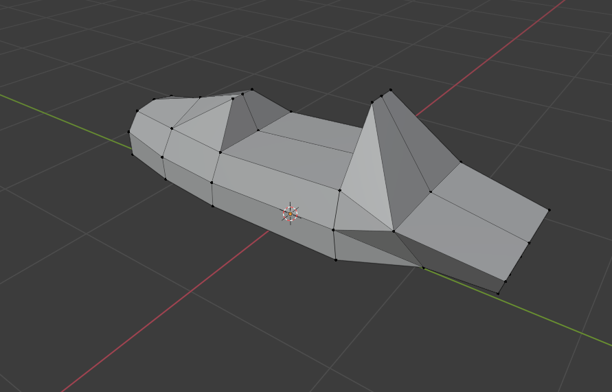
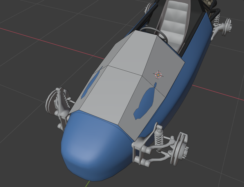
Here’s a quick one example :
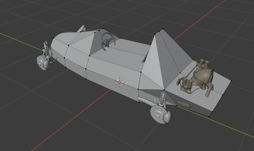
And here’s a picture of it on its own.
When it comes to designing jbeam, experience is fairly important, however if you follow the guidelines listed earlier you shouldn’t run into major issues.
-
You don’t need your structure to be nearly as accurate as you might think. At the end of the day it mainly needs to collide and deform reasonably well.
-
If you can have nodes pulling double duty as structural elements and as attaching for suspension/steering elements if possible, that can help simplify the structure. For example here, this node is going to be used both as part of the chassis’s main jbeam structure, and as a shock mount.
- In most chassis’ jbeam, you can often identify a “spine”, or some sort of box section which will act as the main rigid structure of your chassis. This part needs particular attention to ensure the vehicle is rigid while driving around.
Setting up the nodes
Node naming
An important part when setting up nodes is to come up with a naming scheme. This is particularly important for central components like the chassis, which require a lot of nodes and have a lot of components connected to it. Good naming makes it much easier to understand which node is which when jbeaming in a text editor, and also helps when it comes to fine-tuning the jbeam. In this case since you have a fairly simple structure, you can use a naming scheme similar to this:
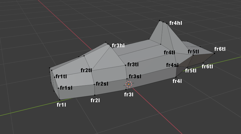
Each node uses a “fr” prefix, identifying the node as being part of the frame. The number matches which “row” it is located in the jbeam structure. The suffix tells us where it is in the row. “t” is used for the top of the main box structure, “s” for the side-pod beams, and “h” for the roll-hoop structures. And the last letter tells us if it’s on the left or right of the chassis.
Your naming scheme can be whatever you like, the two most important rules is that it must make sense for you, and you should have “symmetry” in the naming with l/r suffixes. You can include things like rr/ll and more when your chassis is wider than 3 nodes. As with anything jbeam related, vanilla cars can be a good source of inspiration.
Header and settings
The chassis template file comes with a predefined “header” for the nodes."nodes":[
["id", "posX", "posY", "posZ"],
{"selfCollision":true},
{"collision":true},
{"nodeMaterial":"|NM_METAL"},
{"frictionCoef":0.6},
{"group":"FormulaBeeSpaceframe"},
{"nodeWeight":3.0},
["node1", 0.00, 0.00, 0.00],
{"group":""},
],
The first line is the table header, which should always be present or else you’ll run into errors. The following lines are usually always put at the start to avoid the jbeam getting affected by “leaking” parameters from other jbeam files, but they can be used elsewhere in the node section as required.
For more information on what each of them does, you can check the nodes page.
The next step consists in creating the nodes one by one, using the coordinates from the dummy jbeam we’ve designed in Blender earlier. You don’t need to copy the thing to the smallest decimal. 3 decimal is good enough for most uses.
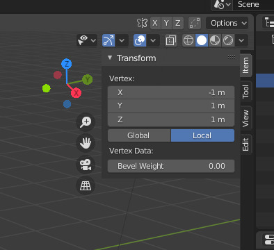
To get the node coordinates in blender, click the small arrow in the upper right corner.
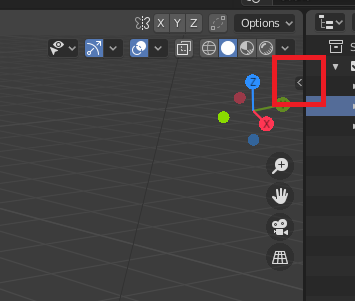
And then click on any node. You should see something like this. Make sure that the origin of the part is centered as well, otherwise the coordinates will be incorrect.
When making nodes, it can be interesting to split up the nodes in “sections”, using comments to help know what’s what.
Another useful tip is to make liberal use of copy pasting. For example if we take the nodes that make up a single row “floor”, are identical with the exception of the prefix and the X coordinates, which is 0 for the center nodes and negative for the right-hand nodes. This means we can just make the left-hand nodes, then copy paste it and just change the bits that need to be changed.
Here’s what your node section should roughly look like.
"nodes":[
   ["id", "posX", "posY", "posZ"],
   {"selfCollision":true},
   {"collision":true},
   {"nodeMaterial":"|NM_METAL"},
   {"frictionCoef":0.6},
   {"group":"FormulaBeeSpaceframe"},

   {"nodeWeight":2.0},
   //Floor
   ["fr1l", 0.294, -1.311, 0.205],
   ["fr2l", 0.416, -0.805, 0.205],
   ["fr3l", 0.465, -0.298, 0.205],

   ["fr1", 0, -1.311, 0.205],
   ["fr2", 0, -0.805, 0.205],
   ["fr3", 0, -0.298, 0.205],

   ["fr1r", -0.294, -1.311, 0.205],
   ["fr2r", -0.416, -0.805, 0.205],
   ["fr3r", -0.465, -0.298, 0.205],
   {"group":""},
],
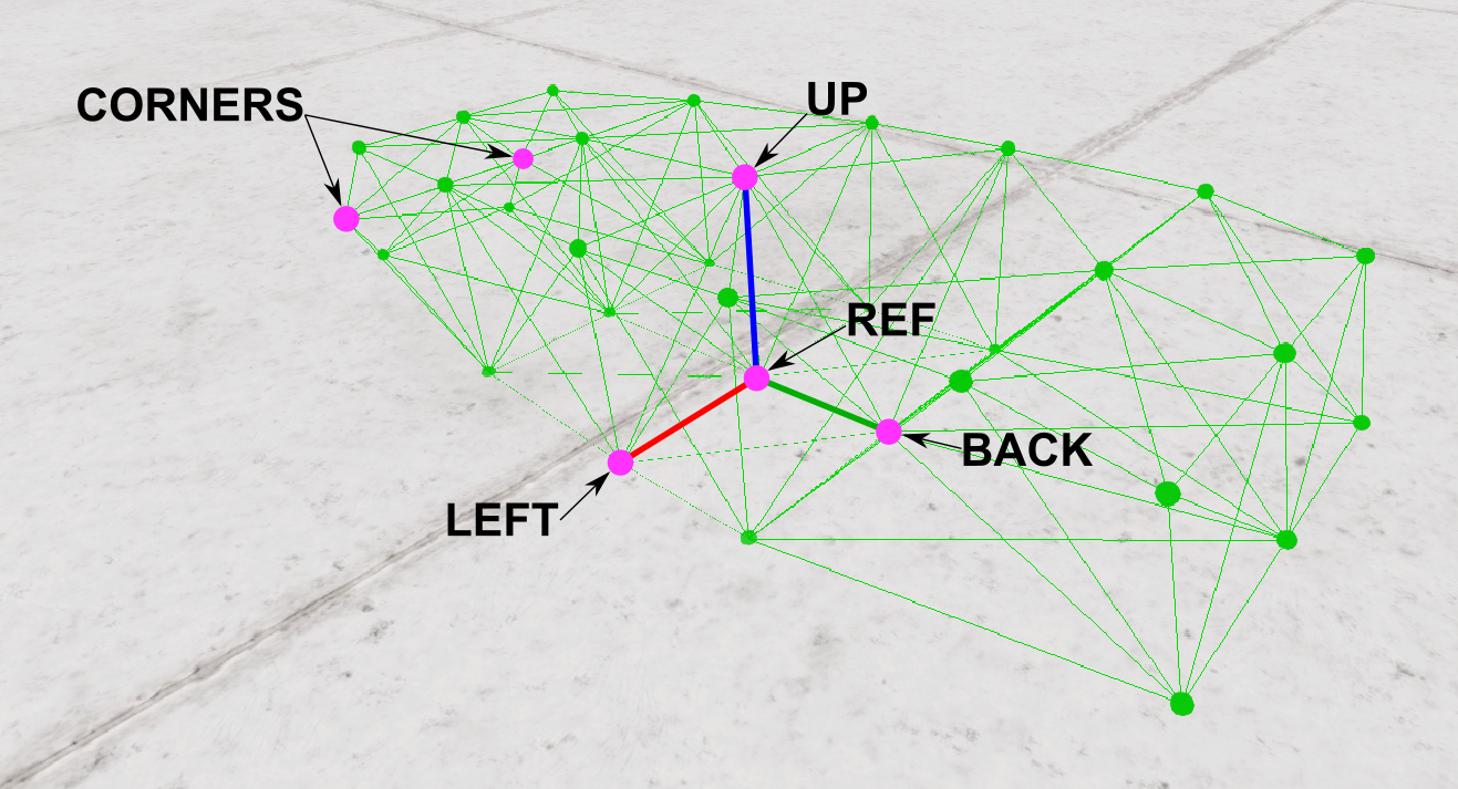
Setting up refnodes
The next step if to define the vehicles refnodes, which are used by the game to define the orientation and basic dimensions of the car, as well as the position of the camera. For more information you can read the refnodes page.
It is important that the nodes align perfectly with each other. If you do not have nodes that are aligned correctly, you might be able to adjust some of your nodes in order to have them line up correctly. The “Up:” node is usually the most problematic, and on some vanilla cars, an “upref” node is created specifically for this purpose, however when it comes to cars with a boxy chassis like this project, it can usually be avoided.
Setting up the beams
As with nodes, beams have a few settings, which are often set initially to avoid the beams get affected by parameters set in other components.
"beams":[
    ["id1:", "id2:"],
    {"deformLimitExpansion":1.2},
    {"beamPrecompression":1, "beamType":"|NORMAL"},
    {"beamSpring":1201000,"beamDamp":150},
    {"beamDeform":50000,"beamStrength":"FLT_MAX"},
],
For more information, see the beams page.
Creating beams is fairly straight forward, and only requires specifying two nodes that you want a beam to appear between them.
As with nodes, it is recommend to split up your beams in sections, to make it easier to fine tune later. An example would be to split them by area and direction. For example all the longitudinal beams in the floor are their own section, crosses in the floor their own section as well, etc.
As with nodes, you can make liberal use of copy pasting. The “replace” function can also be used quite a lot. For example when making the longitudinal floor beams you can write the beams for the left side, and then copy-paste them and replace the “l” suffix with “r” for the right side.
Do note that at this point, even if you haven’t finished creating the beams, you should be able to load the car and use the debug views to see where you need to add beams. Keep in mind though that the whole structure might collapse on spawn, and keeping the physics paused with the J key might be useful.
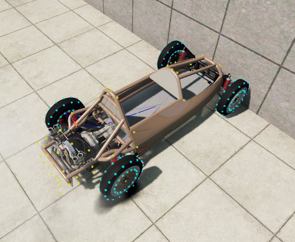
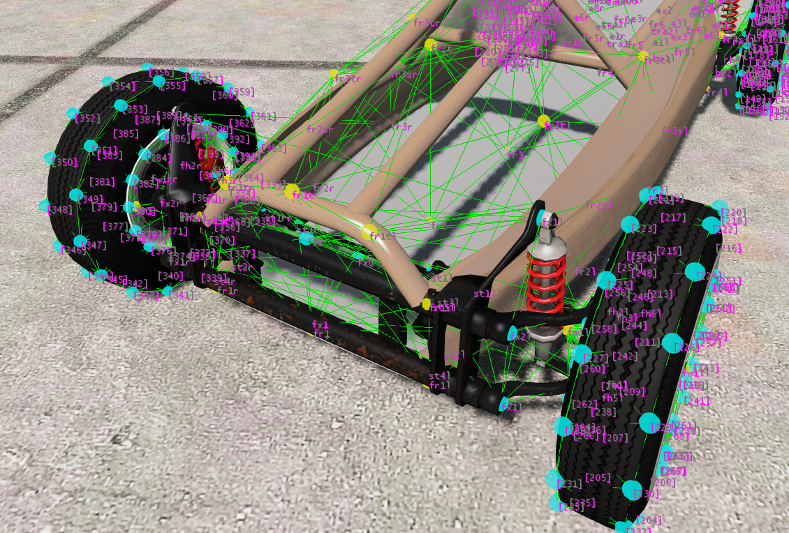
To view the nodes and beams in game, use the debug modes . You can use keyboard shortcuts for cycling between different modes: Ctrl + M for node visualization, Ctrl + N for node text such as names and positions, and Ctrl + B and for beam visualization. You might also find Ctrl + T for triangle visualization useful later.
Each time you save a change in the jbeam file, you can press Ctrl + R in-game to update the jbeam. Check the next section for more details.
Creating the beams is a fairly time consuming step, but it’s very important to keep your beams tidy in order to make sure your structure is easy to fix and adjust afterward. Don’t forget to properly brace the structure as shown in the basic principles . If the structure wobbles on spawn it might need to add more bracing in the direction of the movement.
You might run into instability issues, signified by the game pausing itself shortly after spawn, or in less extreme cases, the structure vibrating violently. They are typically caused by too high beamSpring and/or beamDamp on some beams, or too low nodeWeight on some nodes. In order to find out which specific nodes are causing the issue, cycle into the “Forces” visualization mode of the nodes, and look for big red force spikes in slow motion. Slow motion can be accessed in the “Environment” menu, or by pressing Alt + Up.
Here’s an example of what your beams section should look like.
"beams":[
    ["id1:", "id2:"],
    {"deformLimitExpansion":1.2},
    {"beamPrecompression":1, "beamType":"|NORMAL"},
    {"beamSpring":1201000,"beamDamp":150},
    {"beamDeform":50000,"beamStrength":"FLT_MAX"},

    //floor
    //length floor
    ["fr1l","fr2l"]
    ["fr1","fr2"]
    ["fr1r","fr2r"]

    //lat floor
    ["fr1l","fr1"]
    ["fr1","fr1r"]

    //cross floor
    ["fr1l","fr2"]
    ["fr1","fr2l"]
    ["fr1r","fr2"]
    ["fr1","fr2r"]
],
Setting up triangles
The two main purposes of triangles are to allow for collisions between vehicles, as well as for aerodynamic drag.
As with the other sections, the chassis template should already have a “triangles” section with a header.
"triangles": [
    ["id1:","id2:","id3:"],
    {"dragCoef":10},
    {"groundModel":"metal"},
    {"triangleType":"NORMALTYPE"},
    ["node1","node2","node3"]
],
For more information on what each property does, check the triangles page.
When creating triangles, you should load the car in so you can visualize your progress as you go. After changing and saving the files, you can press Ctrl + R
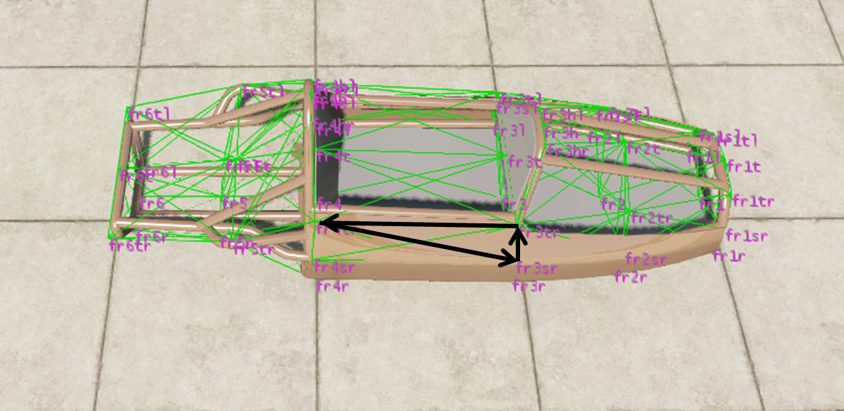
Making triangles consists in taking 3 nodes in a counterclockwise order. For example, here we’d have fr3sr->fr3tr->fr4tr.
Then repeat this for every surface on the chassis. Here’s an example of what a few triangles should look like.
"triangles": [
    ["id1:","id2:","id3:"],
    {"dragCoef":10},
    {"groundModel":"metal"},
    {"triangleType":"NORMALTYPE"},
    ["fr1", "fr1r", "fr2r"],
    ["fr1", "fr2r", "fr2"],
    ["fr1l", "fr1", "fr2"],
    ["fr1l", "fr2", "fr2l"],
    ["fr2l", "fr2", "fr3"],
    ["fr2l", "fr3", "fr3l"],
],
Setting up flexbodies
"flexbodies":[
    ["mesh", "[group]:", "nonFlexMaterials"],
    ["TutoFBee_Spaceframe", ["FormulaBeeSpaceframe"]],
    ["TutoFBee_Body", ["FormulaBeeSpaceframe"]],
],
The next section that you need to change is the flexbodies section near the top of the file, which are the visible models that will be used for the car. For more information on the various properties of flexbodies you can see the flexbodies page.
Flexbodies require a group to be defined, which is referenced in the nodes section. Flexbodies are mapped to the nodes with the same group as them, so make sure to use the same group name as you did in the Nodes section previously.
Non-removable body panels can use the same group as the body itself, this way they won’t need separate nodes with a different group to be added.
Spawning the car in-game and adjusting the beam parameters.
At this point you should have everything you need to spawn the car in-game.
In case you encounter any issues, look at the common issues page.
At this step, as the car isn’t drivable, the main things you need to look out for is to make sure that the model shows up correctly, and that there are no visible issues with lack of structural rigidity or vibration.
Once everything seems good you can move to the next point.
Attaching the suspension, steering and drivetrain.
Introduction to degrees of freedom
Each component or node has a total of 6 degrees of freedom, which refers to how they can move. These are translation on all 3 axes, and rotation around all 3 axes. If you want a component to be fixed solidly to the chassis, it is important to “lock” all 6 degrees of freedom.
Fixing a component in rotation
Fixing a component in rotation is done by connecting a certain number of nodes of a component. If you connect only a single node, the part will be fixed in translation, but allowed to rotate around any axis.
If you connect two nodes, the part will be allowed to rotate along the axis made by those two nodes. This can be useful for components like doors, suspension, etc, where movement can be desirable, but needs to be restrained.
If you connect three or more nodes, the part will be fixed in all three axis of rotation. This will be the desired result of all components in this section.
Keep in mind as well that in some cases, especially body panels, you might want to have the part be fully fixed on spawn, but break in a way where only two nodes end up connected. This is obvious with doors for example, where the latch acts as a “third connection”, and allows the door to swivel when the latch is broken. We will be going into more detail about this later in the guide.
Fixing a component in translation
To fix a node in translation, you need to have at least three beams, or essentially one per axis of movement.
When combined with a sufficient number of attachment points, as described in the previous section, this should allow for a component that is rigidly fixed in place.
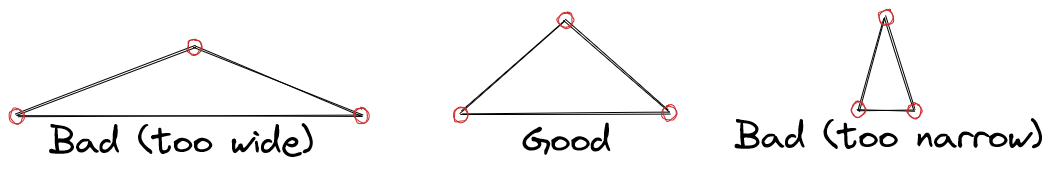
Keep in mind that the three beams do not have to be perfectly perpendicular to one another; however they should still be somewhat perpendicular to each other.
If the “tripod-like” structure that will holds a node in place is too narrow, this will cause higher stresses in the beams, resulting in an effectively less rigid structure. Same thing is the tripod is too wide, as it will cause the node to be more prone to “reversals”
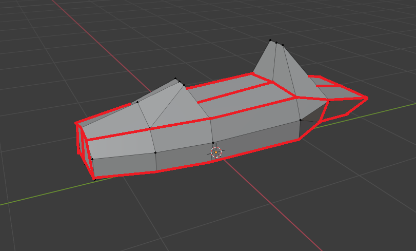
A note about the length of beams
It’s important to make sure that the beams that lock a certain direction of movement are all reasonably long, so their angle doesn’t change significantly under minor deformation.This is a common mistake with door latches, where some people only use a single very short beam connecting the door to the pillar, causing the door to flop around. The proper way would be to have beams connecting the door to a more central position in the car, like the transmission tunnel.
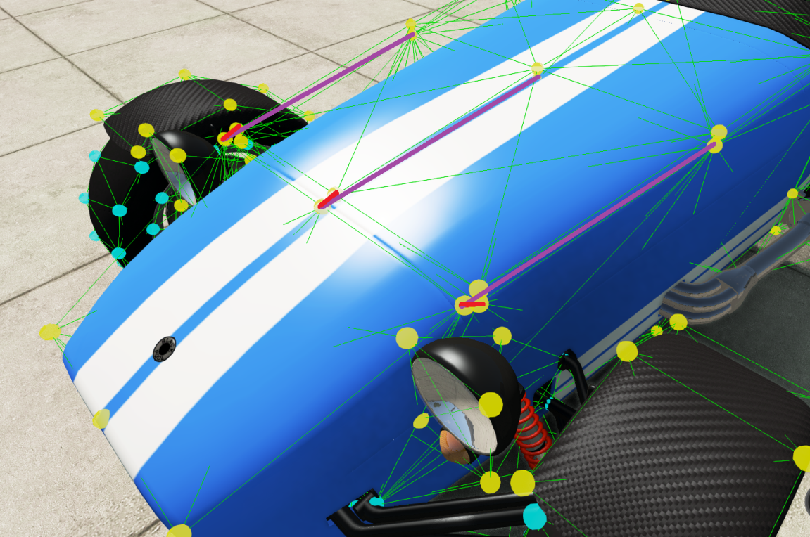
For a more visual example, let’s use the Superlite’s nosecone and the beams preventing it from moving backward. If you make very short beams like those shown in red, any small amount of movement of the nosecone will bring those beams at an angle where they can’t effectively keep the nosecone from moving backward. Instead, you want to use beams like those in purple, which will be long enough to avoid that issue.
Linking the chassis to the other components
Now let’s take what we’ve learned and use that to attach the suspension components and drivetrain to our chassis. In all cases we’ll be working within those components jbeam files. There’s a pre-defined section with the correct parameters where you can put your beams.
//Chassis mount
{"beamPrecompression":1, "beamType":"|NORMAL"},
{"beamSpring":1501000,"beamDamp":150},
{"beamDeform":30000,"beamStrength":"FLT_MAX"},
//Put the connection beams here


{"beamPrecompression":1, "beamType":"|NORMAL", "beamLongBound":1.0, "beamShortBound":1.0},
When making beams to connect separate components together, it works the same way as making any beam. As long as the two nodes exist within the vehicle, the game will create a beam, even if the nodes are defined within different files.
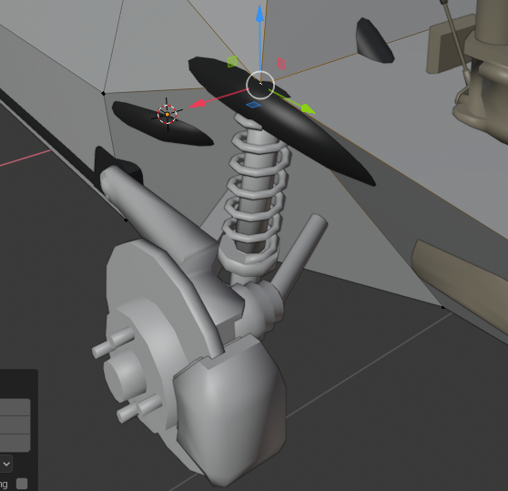
Front suspension and steering
The included suspension beam and steering setup is pretty much self-contained, so it only needs to be solidly attached to the chassis.
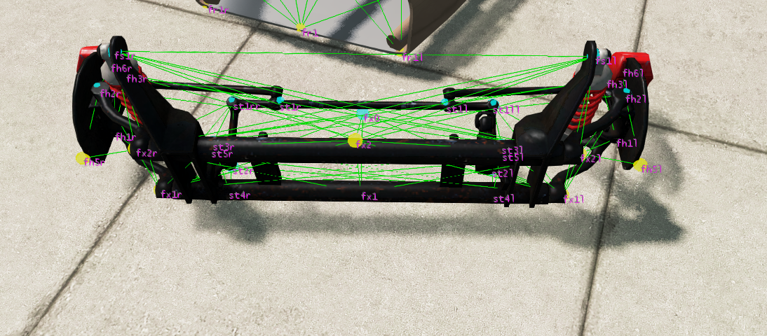
The most important part is to use nodes that don’t move while driving, like the suspension arm mounts on the beam itself, which are fx1l/r and fx2l/r.
As mentioned earlier, for each of those nodes you should have at least 3 beams, holding the suspension solidly on all 3 axis.
Here’s an example of what your added beams might look like.
//Chassis mount
{"beamPrecompression":1.0,"beamType":"|NORMAL", "beamLongBound":1.0, "beamShortBound":1.0},
{"beamSpring":1501000,"beamDamp":150},
{"beamDeform":30000,"beamStrength":"FLT_MAX"},
//Put the connection beams here

["fx1r","fr2r"]
["fx1r","fr1"]
["fx1r","fr1tr"]
["fx2r","fr2r"]
["fx2r","fr1"]
["fx2r","fr1r"]

["fx1l","fr2l"]
["fx1l","fr1"]
["fx1l","fr1tl"]
["fx2l","fr2l"]
["fx2l","fr1"]
["fx2l","fr1l"]
Rear suspension arms
The rear suspension has the suspension pivot nodes predefined, and as with the front suspension, those just need to be solidly attached to the chassis.
The coilovers however will need to be modified to attach them to the body.
For the suspension arms, the process is the same as with the front, however this time the nodes we’ll be using are the trailing arm pivot nodes, which are bx1r/l and bx2r/l.

Coilovers
If you scroll down to the “TutoFormulaBee_coilover_R_race” component, you should see a beam section with a lot of stuff in it.
"beams": [
    ["id1:", "id2:"],
    //rear springs - no soft bumpstop - advanced dampers
    //motion ratio ~0.74
    {"beamType":"|NORMAL"},
    {"beamDeform":12000,"beamStrength":140000},
    {"beamSpring":"$spring_R","beamDamp":0},
    ["rh4r","fr5tr", {"precompressionRange":"$=($springheight_R + 0.01)*0.74"}],
    ["rh4l","fr5tl", {"precompressionRange":"$=($springheight_R + 0.01)*0.74"}],
    //rear dampers
    {"beamPrecompression":1, "beamType":"|BOUNDED", "beamLongBound":1.0, "beamShortBound":1.0},
    {"beamLimitSpring":0,"beamLimitDamp":0},
    {"beamSpring":250,"beamDamp":"$damp_bump_R"},
    ["rh4r","fr5tr", {"beamDampRebound":"$damp_rebound_R","beamDampVelocitySplit":0.2,"beamDampFast":"$=$damp_bump_R / 3","beamDampReboundFast":"$=$damp_rebound_R / 3","dampCutoffHz":500,
        "soundFile":"event:>Vehicle>Suspension>car_vint_sml_01>spring_compress_01","colorFactor":0.8,"attackFactor":10,"volumeFactor":2.4,"decayMode":1,"decayFactor":10,"pitchFactor":0.4,"maxStress":13}],
    ["rh4l","fr5tl", {"beamDampRebound":"$damp_rebound_R","beamDampVelocitySplit":0.2,"beamDampFast":"$=$damp_bump_R / 3","beamDampReboundFast":"$=$damp_rebound_R / 3","dampCutoffHz":500,
        "soundFile":"event:>Vehicle>Suspension>car_vint_sml_01>spring_compress_01","colorFactor":0.8,"attackFactor":10,"volumeFactor":2.4,"decayMode":1,"decayFactor":10,"pitchFactor":0.4,"maxStress":13}],
    //bumpstop and extension limiter
    {"beamSpring":0,"beamDamp":0},
    {"beamLimitSpring":251000,"beamLimitDamp":5000},
    ["rh4r","fr5tr", {"longBoundRange":0.12,"shortBoundRange":0.12,"boundZone":0.04,"beamLimitDampRebound":0,"dampCutoffHz":500}],
    ["rh4l","fr5tl", {"longBoundRange":0.12,"shortBoundRange":0.12,"boundZone":0.04,"beamLimitDampRebound":0,"dampCutoffHz":500}],
    {"beamLimitSpring":0,"beamLimitDamp":0},
    {"beamPrecompression":1.0, "beamType":"|NORMAL", "beamLongBound":1, "beamShortBound":1},
],
While this might seem intimidating at first, it’s essentially just 6 beams with a lot of added properties. One set represents the springs, one then dampers and the other one serves as bump stops. In all cases you should see these two references to nodes, with rh4r/l being the shock mount on the swing arm, and bs1r/l being the autobello’s upper shock mount.
["rh4r","bs1r", {"precompressionRange":"$=($springheight_R + 0.01)*0.74"}],
["rh4l","bs1l", {"precompressionRange":"$=($springheight_R + 0.01)*0.74"}],
What you need to do is replace bs1r/l with the node you’ll be using as an upper shock mount.
To ensure decent handling, the upper shock mount should be located directly above or slightly in front of the shock mount on the arm.
Having the node positioned incorrectly can cause the suspension to be effectively too soft, resulting in wobbly handling.
When spawning the car in with those changes, you might notice a problem; the shocks don’t appear, even if their beams show up.

This issue is related to the shocks nodegroups.
"flexbodies":[
    ["mesh", "[group]:", "nonFlexMaterials"],
    ["autobello_coilover_R", ["shockbottom_R", "shocktop_R"]],
],
While the “shockbottom_R” group exists, and is defined by the lower shock mount nodes on the suspension arms, you need to define the upper shock mount nodes as being part of the “shocktop” node group. The best way to do that is to add the shocktop deform ground “in-line” of the shockmount nodes, like this :
["fr4tl", 0.34, 0.655, 0.645],
["fr5tl", 0.454, 1.034, 0.556, {"group":["FormulaBeeSpaceframe","shocktop_R"]}],
["fr6tl", 0.384, 1.627, 0.457],
Just make sure to triple check syntax, in order to avoid issues when trying to load the car.
Once you’ve added that to both shock mounts, the coilovers should show up when you reload the vehicle.
Engine and transmission
Engines can usually be attached in two ways. The first one, which works easily with engines jbeamed as cubes, is to just solidly attach all 4 top corners to the chassis.
However in our case, we’ll be using pre-defined engine mount nodes, namely em1r/l on the engine side, and “tra1” on the gearbox side. This is a bit more realistic, and more similar to how engines are fixed IRL.
Depending on the way your chassis is designed, you might need either 3 or 4 beams per engine mount to properly fix the engine in place.
//Chassis mount
{"beamPrecompression":1, "beamType":"|NORMAL"},
{"beamSpring":1501000,"beamDamp":150},
{"beamDeform":30000,"beamStrength":"FLT_MAX"},
//Put the connection beams here

["em1r","fr6r"]
["em1r","fr5r"]
["em1r","fr5l"]
["em1r","fr4r"]

["em1l","fr6l"]
["em1l","fr5l"]
["em1l","fr5r"]
["em1l","fr4l"]
For the gearbox, since the engine mount nodes already take care of keeping the engine from moving forward and back, the beams mostly need to be set-up in a way to prevent the engine/gearbox assembly from rocking back and forth.
//Chassis mount
{"beamPrecompression":1, "beamType":"|NORMAL"},
{"beamSpring":1501000,"beamDamp":150},
{"beamDeform":30000,"beamStrength":"FLT_MAX"},
//Put the connection beams here

["tra1","fr4t"]
["tra1","fr4l"]
["tra1","fr4r"]
Fuel tank
You might have noticed a “fuel tank” file in the jbeam. The included file already works as a fuel tank, even though it does not have any nodes and beams. However, for practice, you should try building your own fuel tank as an 8 node cube, using the things you learned earlier in the tutorial.
The only twist is that you should identify one of the beams as the “fuel beam” so it changes the weight of the fuel tank based on the quantity of fuel in the tank.
This can by adding some properties “inline”, like with the shock top node group.
["f1r", "f1l",{"name":"fuelTank","containerBeam": "fuelTank"}],
Testing and adjusting the suspension and engine mounts
At this point, if you have followed the guide properly and the car loads, you should have a fully drivable car with steering and suspension. Here comes the fun part, which is to make sure that everything works as it should, and doesn’t flex in ways that it should.
In all cases, your best tools for debugging are the slow-mo function, and the stress view in the beam debug menus Ctrl + B.
The first part is to make sure that everything is at least somewhat rigid. To check that, simply drive the vehicle around, and see if you notice any unexpected movement. If you see anything weird going on, try to identify which way the component is moving, and add or adjust beams to counteract that movement.
Once the suspension is mostly rigid, it is now time to stress test it, and try to make sure it can also handle so more spirited driving.
Let’s start with the rear suspension. The best way to see if any powered axle works as it should is to do a wall-stand burnout, essentially resting the nose of the car on a wall and making a burnout.
If you see any oscillation, switch to slow motion and look at which nodes are moving and in what direction.
You will need to rigidify those nodes by changing/adding beams to more rigidly fix movement in that direction. While raising beamspring can also help, the predefined beamspring and damp values in the template should be roughly correct, and you should prioritise adjusting the topology of your jbeam first, as it is impossible to properly rigidify sub-optimal jbeam just by raising the beamspring.
For the front suspension, the best way induce oscillations is to get a decent bunch of speed, and then brake to the point of locking the wheels. Once again, if you have unwanted oscillations, use slow motion and the debug tools to find the exact way those deformations are happening.
For the front specifically, while the guide says to use fx1r/l and fx2r/l to attach the suspension beam to the chassis, you might need to add more beams attaching to the nodes to the other fixed components of the front suspension beam, namely fx1/2, which are in the center of the suspension, and fs1r/l, which are used as shock mounts.
Since all those components do not move relative to the chassis, adding connections from those beams to the chassis might help keep the front suspension from vibrating and oscillating without affecting the functionality of suspension.
Body panels and other breakable body parts
The next step is to add in the body panels. This guide has sections for both flat panels like hoods, and boxier components like a nosecone. You should however be able to follow this guide for any panel you have.
All panels usually involve breakable connections, which will allow the panel to break off in crashes.
If you have a separate component whose shape could easily be translated to a box jbeam, like a nosecone, jbeaming it should be fairly similar to what you’ve already done, other than the elements mentioned previously.
If you have a fairly flat panel, like a door, hood, trunk, etc; where you cannot use the same boxy structure we used before, you will need to use a rigidifier node. We’ll go over that further down in this section. Keep in mind that even hoods with some depth (like the hood on a Jeep for example) will often still require the use of a rigidifier node, as they aren’t deep enough to ensure that the structure stays rigid in all conditions.
Adding slots and creating new parts The first step is to create the slots and base parts we need for our body panels. In most cases, all of them will be under the “chassis”, so let’s start by opening up that file, and going to the “slots” section. For more information on slots and parts, you can refer to the introduction to the part/slot system , and the page about the slot and slottype sections.
To add more slots to the chassis, you can start by copy-pasting the header of the slots section, to have as many new entries as we have parts. For example, if you had two, it would look like this :
"slots":[
    ["type", "default", "description"],
    //Engine
    ["TutoFormulaBee_engine","TutoFormulaBee_engine", "Engine"],
    ["TutoFormulaBee_fueltank","TutoFormulaBee_fueltank", "Fuel Tank"],
    //Running gear
    ["TutoFormulaBee_suspension_F","TutoFormulaBee_suspension_F", "Front Suspension"],
    ["TutoFormulaBee_suspension_R","TutoFormulaBee_suspension_R", "Rear Suspension"],
    //Panels
    ["type", "default", "description"],
    ["type", "default", "description"],
],
Then you want to put the desired slot name into “type”, and the name of the default part as “default”. You can use the other slots as an example of slot naming, including the use of prefixes as with materials and meshes. For the default part, while we haven’t created any parts yet, it’s good practice with slots that have a single option to name the only part the same as the slot.
With a hood and nosecone, the end result will look like this:
"slots":[
    ["type", "default", "description"],
    //Engine
    ["TutoFormulaBee_engine","TutoFormulaBee_engine", "Engine"],
    ["TutoFormulaBee_fueltank","TutoFormulaBee_fueltank", "Fuel Tank"],
    //Running gear
    ["TutoFormulaBee_suspension_F","TutoFormulaBee_suspension_F", "Front Suspension"],
    ["TutoFormulaBee_suspension_R","TutoFormulaBee_suspension_R", "Rear Suspension"],
    //Panels
    ["TutoFormulaBee_nosecone", "TutoFormulaBee_nosecone", "Nose Cone"],
    ["TutoFormulaBee_hood", "TutoFormulaBee_hood", "Hood"],
],
The next step is to create the base of the parts themselves. For this, you can check in the “TutoFormulaBee_panels.jbeam” file, which includes a template for a new component. You can copy that part so you have as many parts as you need. In the previous example that means 2 copies. When creating new parts, make sure to copy the entire part including the name and the end bracket.
Once you’ve created as many copies as you need, change the part’s name and slottype to match the slots you created earlier.
Intro to break groups
One major feature of most body panels is their ability to break off in crashes. This can be done using the “beamStrenght” property, and giving it a value other than “FLT_MAX”, which will allow the connection beams to break when stress goes above a certain level.
However, as mentioned previously, each connection point needs a few beams to make sure that it is nice and rigid. How do we ensure that all those beams break at the same time? This is where break groups come in. Break groups identify a group of beams, and tells the game that if any of those beams break, all the other beams in the group should get broken at the same time.
Example:
//attach beams
{"beamDeform":15000,"beamStrength":15000},
{"breakGroup":"frontHood"},
["hood1ll","fr1l"]
["hood1ll","fr1"]
["hood1ll","fr2l"]
Rigidifiers
One specific challenge when it comes to jbeaming flat components like hoods and doors, is that their flat shape doesn’t allow to make a nice and rigid component. It will tend to fold on itself.The fix is to use what we call a “rigidifier node”, which is a node with collisions disabled, located some distance away from the surface.
One thing to keep in mind is that the beams connecting the rigidifier to the surface nodes should have a lower “beamDeform” compared to the beams that make up the panels surface. This will ensure that the panel will deform mostly by “folding”, which is how it would happen IRL.
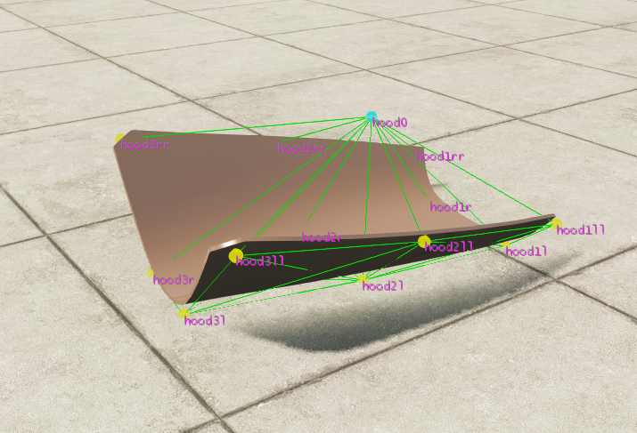
Building the hood (flat panels)
The first part of building a hood is done in a similar fashion to making any surface on the chassis. One thing to keep in mind is that panels should preferably be at least 3x3 nodes, to make sure that they can fold on themselves.
As for the rigidifier node, you can start by placing it .5 meters away from the surface, and adjusting as needed. It also needs to have collisions disabled, as it’s not a physical component in the structure. This done using the “collision:false” and “selfCollision:false” statements.
"nodes":[
    ["id", "posX", "posY", "posZ"],
    {"selfCollision":true},
    {"collision":true},
    {"nodeMaterial":"|NM_METAL"},
    {"frictionCoef":0.6},
    {"group":"TutoFBee_Hood"},
    {"nodeWeight":2.0},
    ["hood1l", 0.177, -1.297, 0.564],
    ["hood1r", -0.177, -1.297, 0.564],
    ["hood2l", 0.167, -0.851, 0.7],
    ["hood2r", -0.167, -0.851, 0.7],
    ["hood3l", 0.115, -0.403, 0.838],
    ["hood3r", -0.115, -0.403, 0.838],

    {"selfCollision":false},
    {"collision":false},
    ["hood0", 0, -0.851, 0.3]  //Rigidifier mod
    {"selfCollision":true},
    {"collision":true},
    {"group":""},
],
For beams it tends to be fairly simple, and just involves connecting every single node of the jbeam to the rigidifier.
    //rigidifier
    {"beamDeform":5000,"beamStrength":"FLT_MAX"},
    ["hood1l","hood0"]
    ["hood1r","hood0"]
    ["hood2l","hood0"]
    ["hood2r","hood0"]
    ["hood3l","hood0"]
    ["hood3r","hood0"]
For the connection to the body, most panels tend to be attached with a hinge on one end and a latch at the other.
This means you should structure your attaching beams in a way where you have 2 break groups. This first one being the hinge, which will have 2 attachment points so the panel can rotate when the latch breaks. It should also be the strongest of the two break groups.
The latch can be done with either 1 or 2 attachment points, depending on the shape and size of the panel. It should be significantly weaker than the hinge, to make sure that it breaks first in crashes.
For panels that don’t have a well-defined latch and hinge, like bumpers and bolted on panels, you can split the various attachment points in any way that seems logical. A common set-up is to fix the front and rear of the “hood” panel with 2 separate break groups, one for the front and one for the rear, but both having the same strength as neither really serves as a latch or hinge.
//attach beams
{"beamDeform":15000,"beamStrength":15000},
{"breakGroup":"frontHood"},
["hood1ll","fr1l"]
["hood1ll","fr1"]
["hood1ll","fr2l"]

["hood1rr","fr1r"]
["hood1rr","fr1"]
["hood1rr","fr2r"]
{"breakGroup":"rearHood"},

["hood3ll","fr3l"]
["hood3ll","fr3"]
["hood3ll","fr2l"]

["hood3rr","fr3r"]
["hood3rr","fr3"]
["hood3rr","fr2r"]
{"breakGroup":""},
Don’t forget to add a “breakGroup”:”” at the end, to make sure that the beams following those aren’t included in the breakGroup. Keep in mind that properties “leak” to other parts, so a unterminated breakGroup might result in your engine falling into pieces when the hood breaks off.
Building the nose cone (breakable parts with a box structure)
When it comes to more cubic structures like a nose cone, jbeaming them is fairly straight forward and doesn’t require any rigidifier node. All you need to do is build the box jbeam and attach it to the body using break groups.
Common issues with panels
As before, the common issues page should help with a lot of the issues you might have encountered.
The main one to look out for with body panels specifically is issues with the parts getting pushed on spawn. Keep in mind that each node has a sphere of influence, so you might need to move things a little further apart than you think.
Conclusion
If you’ve followed this entire guide, you should now have a simple but fully drivable car. At this point you can have fun and try adding other things to it, like functional gauges/pedals, which are done using props , additional part options, skins, etc.
Have fun and don’t be afraid to try things :) And as with anything, looking at what others have done can help give you some ideas, or help understand how to build different things.
Was this article helpful?